


X
Wiring Schematics and Diagrams
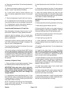
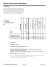
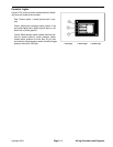
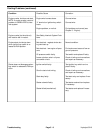
Logic Chart
Each line on the Logic Chart shows the combination of
switch conditions that must be made for the listed action
to occur. Example - START, under ACTIONS: For the
engine to start the Key Switch must be moved to Start
(making terminals B + L + S) and the hydraulic pump
must be in Neutral (Traction Switch 1 CLOSED).
KEY
O
Switch Closed
Switch Open
SWITCHES
Oil Pressure Switch
Wheel Position Switch
Accumulator Charge Switch
Aerator Start (Engage) Switch
Aerator Stop (Disengage) Switch
Lift Switch DOWN (Aerate)
Accumulator High Press Switch
Brake Switch
ACTIONS
1. Start X X
2. Run X X
3. Machine Lower (aerate position) X O X
4. Aerate
(see Controller Ti
Machine Moving (out of neutral) X X X X X X O
Machine Stationary (neutral) X X X X X X O
5. Machine Raise (transport position) X X O
Switch Closed Momentarily
Switch Conditon Not Relevent
Start - Key Switch B + L + S
Run - Key Switch B + L + A
Traction Switch 1
Water Pressure Switch
Traction Switch 2
Lift Switch UP (Transport)
ming below)
Controller Timing
Aerate START-UP Sequence
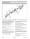
1. Pump clutch engages immediately.
2. Valve clutch engages 5 seconds after pump clutch engages.
Aerate SHUT-DOWN Sequence (Neutral Delay)
1. Pump clutch disengages and green light goes off 4 seconds after transport switch opens (red light goes off).
2. After another 3 seconds, valve clutch will disengage.
NOTE: Keeping aerate start (engage) switch pushed in (closed) will keep green light on and override neutral delay
shut-down.
Aerate SHUT-DOWN Sequence (Disengage Delay)
1. Pump clutch disengages and green light goes off immediately when stop (disengage) switch is pushed in (opens)
or if pump start limit switch or water pressure switch opens (yellow light goes off).
2. After another 3 seconds, valve clutch will disengage.
Wiring Schematics and Diagrams Page 5 - 2 Hydroject 3010