


Hydroject 3010
Page 6 – 20
Repairs
Rev. B
Repairs
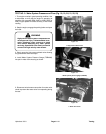
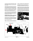
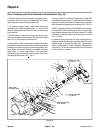
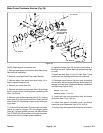
Drive Coupling and Clutch Removal and Installation (Fig. 30)
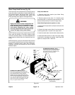
1. Park the machine on a level surface, engage the park-
ing brake, open the hood and disconnect the engine
spark plug wires. Remove guard (Item 38).
2. To remove coupling shaft, remove four capscrews
connecting the rubber couplers (Item 11, 12) to clutch
(Item 8) and adapter hub (Item 16), then lift shaft away
from machine.
3. Clutch (Item 8), pulley (Item 3) and clutch (Item 2) can
now be removed by removing bolt (Item 26) and washer
(Item 27). A puller tool may be required.
4. Apply “Never–Seez“ or equivalent to engine shaft and
pulley shafts. Make sure keys (Item 1 and 4) are properly
installed, then align keyways in clutches and pulley with
keys. Make sure clutch (Item 8) is installed so clutch
angle (Item 7), clutch stops (Item 5, 33) and clutch
bumpers (Item 6) will prevent clutch rotation. The clutch
bumper gap should be 0.22 +
.03 in.
5. Apply Loctite 271 or 680 to threads of bolt (item 26).
Use special washer (Item 27) and install bolt. Remove
engine air cleaner feed hose to access teeth of flywheel.
Hold flywheel and tighten bolt to a torque of 25 – 30 ft–lb.
NOTE: A tapered hub (Item 16) is attached to cam gear-
box input shaft. When installing hub, be sure to use spe-
cial hardened washer (Item18), apply Loctite 271 or 680
to threads of capscrew (Item14) and tighten to a torque
of to 15 ft–lbs.
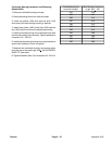
6. Install all bolts and spacers in drive coupling using il-
lustration below. Position flat of spacer (Item10) toward
welded flange of drive shaft (Item 24). Tighten caps-
crews until shoulder of spacer is seated, then tighten to
a torque of 15 ft–lb more than prevailing torque required
to turn locknut on threads.
31
32
33
34
35
36
37
38
39
40
41
42
1234567
8
9
10
16
17
1819
20
21
22
23
24
25
26
27
28
29
30
11
12
13
14
15
6
10
18
14
18
32
31
Clutch bumper gap
0.19 – 0.25 in.
Never–seez
Never–seez
Loctite 271 or 680
25 – 30 ft–lb
Loctite 271 or 680
25 – 30 ft–lb
on engine shaft
Figure 30