


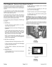
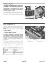
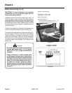

Lift Switch (Fig. 15)
The lift switch is a three position switch. Switch position
is maintained in center position with no circuits made.
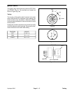
Test the switch by disconnecting the wires from the
switch terminals and connecting a continuity tester or
ohm meter across the terminals.
Terminals 2-3 and 5-6 should have continuity in UP.
Terminals 2-1 and 5-4 should have continuity in DOWN.
1
1
Figure 15
1. Lift switch
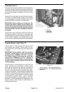
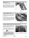
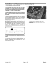
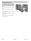
Linear Actuator (Fig. 16)
The linear actuator has a bi-directional electric motor
which engages a clutch and screw mechanism to ex-
tend or retract a rod and raise or lower the transport
wheels.
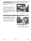
To test the actuator:
1. Disconnect the wiring connector.
2. Connect a 12 volt battery so the negative (–) terminal
is connected to the red wire of the actuator connector.
When the positive (+) battery terminal is connected to
the yellow wire the actuator motor should operate to
extend the actuator cylinder, raising the wheels to aer-
ate position.
Figure 16
3. Connect a 12 volt battery so the negative (–) terminal
1. Linear actuator 2. Wiring connector
is connected to the yellow wire of the actuator connec-
tor. When the positive (+) battery terminal is connected
to the red wire the actuator motor should operate to
retract the actuator cylinder, lowering the wheels to
transport position.
2
1
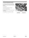
Rod end play 0.070 max.
Current draw 26 amps max.
12 VDC
Speed 3/4 in. per second at maximum
load
Linear Actuator Specifications
Voltage
Testing Page 5 - 20 Hydroject 3010