


Connect Cutting Unit to Traction Unit
1. Center traction unit in front of cutting unit on any flat
hard surface.
2. Raise seat and open needle valve. This allows lift
arms to float freely.
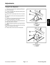
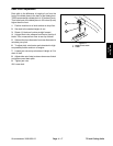
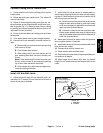
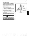
3. Adjust lift arms heights making sure that the ma-
chined surface on top of each traction unit lift arm is par-
allel to ground (Fig. 17). (Raise or lower lift arm casting
by pushing up or down from behind the front tires or us-
ing wrench in front of tractor)
4. Check for dirt and debris on mating parts and clean
as required.
5. Turn castor wheels so they point straight forward.
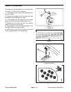
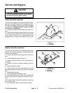
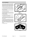
6. Secure first lift arm assembly to traction unit as fol-
lows:
A. Remove hair pin cotter and clevis pin securing
latch cover to lift arm.
B. Pivot release lever upward.
C. Slide cutting unit lift arm onto traction unit lift
arm, inserting shaft latch into slot in traction unit
lift arm.
Note: If latch does not fall into slot in traction unit
lift arm, raise or lower lift arm casting by pushing
up or down from behind the front tires.
D. Pivot release lever downward and tighten se-
curely by rotating clockwise.
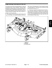
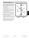
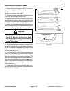
7. Install other lift arm on tractor by rotating deck to-
wards tractor, aligning lift arm to tractor arm and repeat-
ing step 5. If latch does not fall into slot in traction unit lift
arm the arms are not lined up.
A. If lift arms on traction unit are not at the correct
height for deck arms to slide on, push up or down
on lift arm castings from behind the front tires until
deck arm lines up and slides on.
B. If lift arms on deck do not line up side to side.
Rotate castor wheels side ways so deck moves
side to side easier. Move deck side to side until lift
arms line up and slide on.
8. Move deck from side to side to check for tightness
and re–tighten latches, if required.
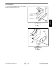
9. Install latch covers to lift arms and secure with clevis
pins and hair pin cotters.
10. Connect drive shaft to traction unit.
11. Close needle valve and lower seat.
12. Start tractor and raise deck to highest possible posi-
tion and turn off engine.
13. Align height–of–cut chains with hole for desired
height–of–cut, install clevis pin and secure with hair pin
cotter.
72 inch
Cutting Units
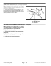
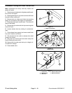
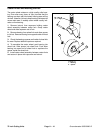
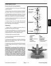
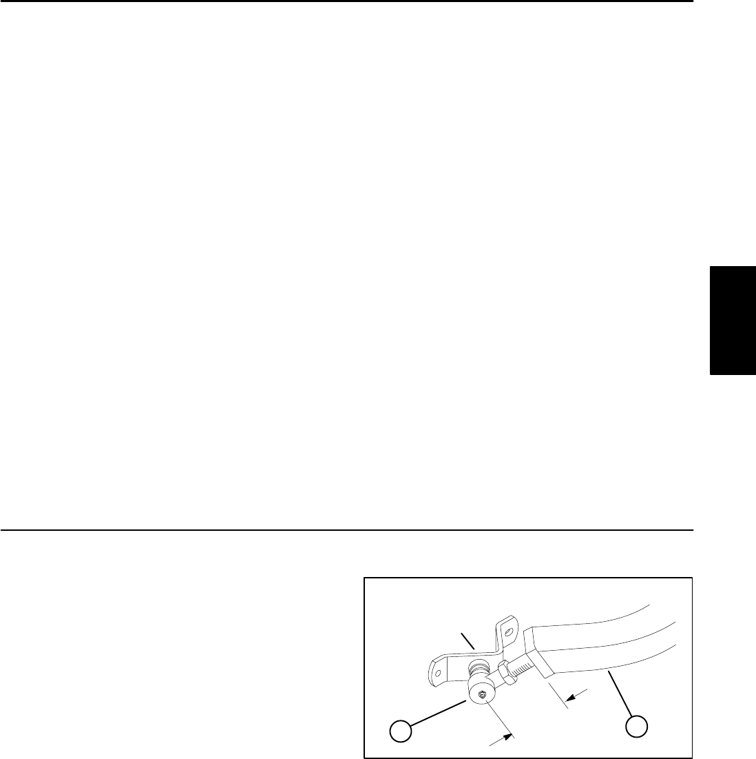
Install Lift Arm Ball Joints
1. Adjust ball joint in each lift arm assembly until a di-
140 ft–lb (19 Kgm)
mension of 2.75 inches (70 mm) from end of lift arm to
center of ball joint is attained.
1
2
2.75 in. (70 mm)
then continue tightening
until slot in nut aligns
with cotter pin hole
Figure 18
1. Ball Joint
2. Lift Arm
Groundsmaster 3000/3000–D
Page 11 – 11
Rev. A
72 inch Cutting Units