


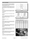
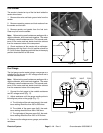
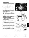
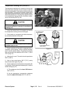
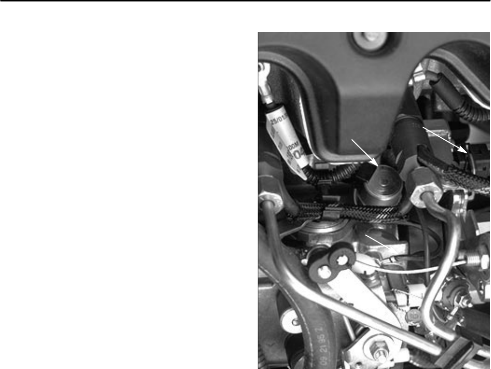
Injection Advance Solenoid (GM 3000–D)
The injection advance solenoid is located on top of the
injector pump, which is on the right side of the engine.
Its has two black wires connected to it. One wire leads
to a connector with orange and white wires. The other
wire is grounded to the injector pump. The solenoid is
powered from the orange (top) wire (Fig. 52).
In Place Testing
Note: Prior to taking small resistance readings with a
digital multimeter, short the test leads together. The me-
ter will display a small resistance value (usually 0.5
ohms or less). This resistance is due to the internal re-
sistance of the meter and test leads. Subtract this value
from from the measured value of the component you are
testing.
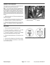
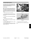
1. Remove wire clip from the connector and discon-
nect connector.
2. Using a digital multimeter, attach one lead to the lug
of the ground wire. Connect other lead to the pin in the
connector that is attached to the injector pump. The
orange wire on the harness connector powers the sole-
noid.
3. The resistance should be about 14.6 ohms.
Live testing
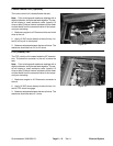
1. Remove wire clip from the connector and discon-
nect connector.
2. Connect a positive (+) test lead from a 12 VDC
source to the pin in the connector that is attached to the
injector pump. The orange wire on the harness connec-
tor powers the solenoid.
3. Touch a negative (–) test lead from the 12 VDC
source to the solenoid body. The plunger should retract
making an audible ”click”.
4. Disconnect the test leads from the solenoid and
connector. Reconnect connector and wire clip.
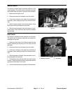
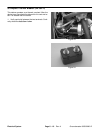
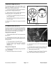
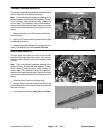
SOLENOID
GROUND WIRE
CONNECTOR
Figure 27
Electrical System
Page 6 – 18
Rev. A
Groundsmaster 3000/3000–D