


H
2
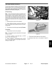
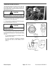
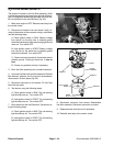
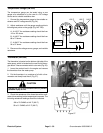
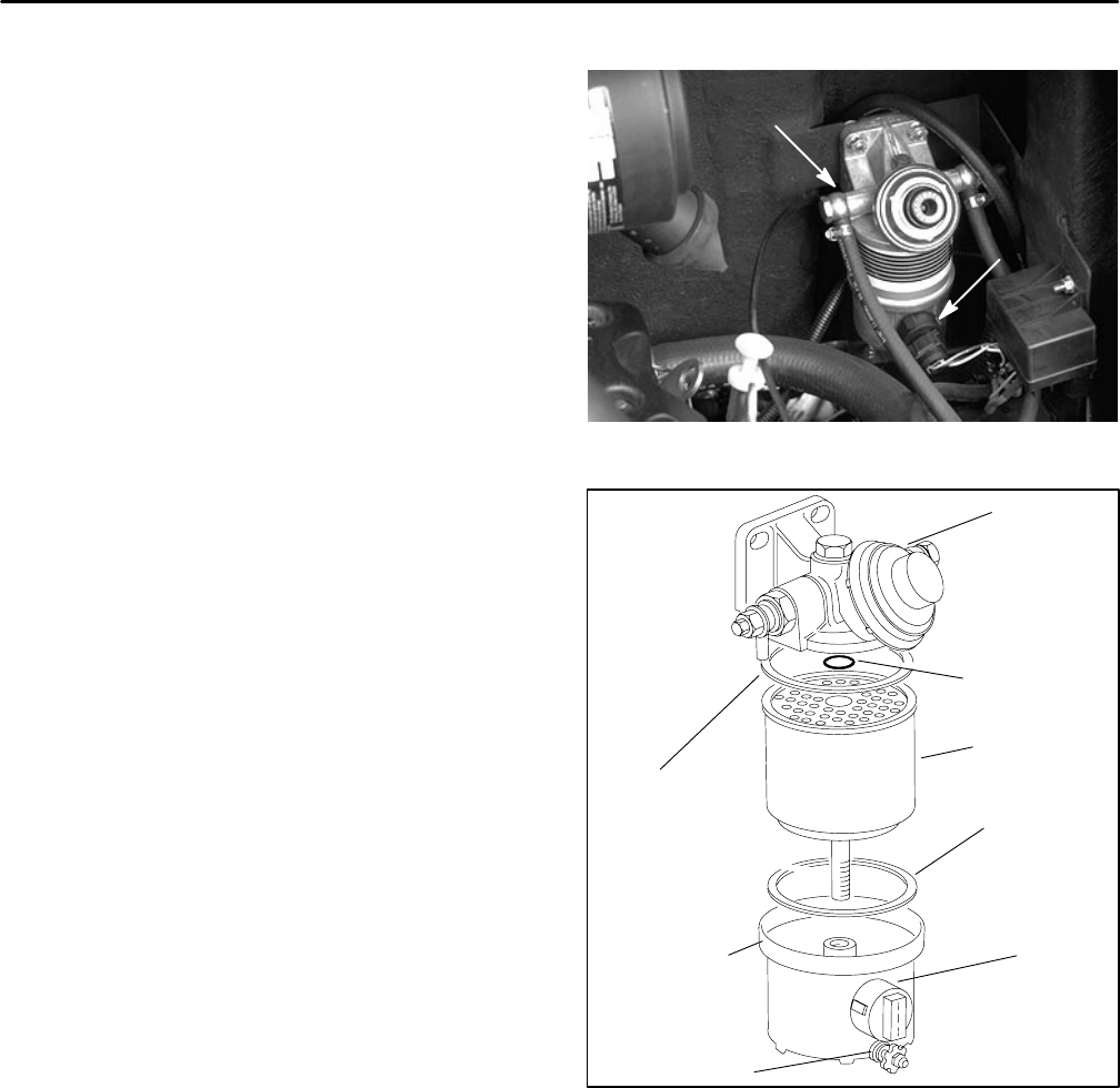
O in Fuel Sensor (GM 3000–D)
The sensor is located on the fuel filter assembly, which
is inside the center shroud area to the left side of the en-
gine. It energizes a red warning light when too much wa-
ter has collected in the fuel filter bowl (Fig. 42).
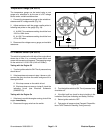
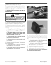
1. Make sure engine is OFF. Remove start relay from
the control center.
2. Disconnect connector from the sensor. Verify cir-
cuitry to the sensor at the connector using a multimeter
and the following steps:
A. Place ignition switch in RUN. Battery voltage
from the pin for the blue wire to chassis ground
should be indicated and the red warning light should
come on. Turn switch OFF.
B. Hold ignition switch in START. Battery voltage
from the pin for the white wire to chassis ground
should be indicated. Turn switch OFF.
C. Check continuity from the pin for the black wire to
chassis ground. Continuity should be 1 ohm or
less.
D. Correct any problem circuitry if necessary.
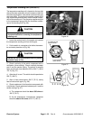
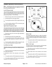
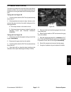
3. Drain fuel filter assembly into a suitable container.
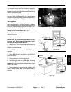
4. Unscrew fuel filter bowl from the assembly. Remove
filter element, gaskets, and O–ring from the assembly.
Store seals in a clean place (Fig. 43).
5. Reconnect connector to the sensor. Fill fuel filter
bowl with tap water.
6. Test sensor using the following steps:
A. Place ignition switch in RUN. The red warning
light should come on. Turn switch OFF.
B. Hold ignition switch in START. The red warning
light should come on. Turn switch OFF.
7. Drain water from the fuel filter bowl. Test sensor us-
ing the following steps:
A. Place ignition switch in RUN. The red warning
light should stay off. Turn switch OFF.
B. Hold ignition switch in START. The red warning
light should stay off. Turn switch OFF.
SENSOR
FILTER ASSEMBLY
Figure 42
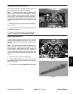
BOWL
GASKET
GASKET
SENSOR
DRAIN
PLUG
ELEMENT
O–RING
FUEL FILTER
FILTER
FILTER
ASSEMBLY
Figure 43
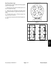
8. Disconnect connector from sensor. Reassemble
fuel filter assembly. Reconnect connector to sensor.
9. Replace sensor with new one if necessary.
10. Reinstall start relay to the control center.
Electrical System
Page 6 – 24
Groundsmaster 3000/3000–D