


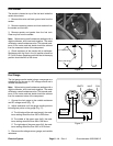
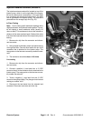

Fuel Sender
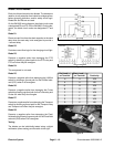
The sender is located on top of the fuel tank inside the
center shroud area.
1. Remove blue wire and black ground wire from the
sender.
2. Remove remaining screws and lock washers from
the sender and fuel tank.
3. Remove sender and gasket from the fuel tank.
Clean any fuel from the sender.
Note: Before taking small resistance readings with a
GROUND WIRE
BLUE WIRE
Figure 15
digital multimeter, short test leads together. The meter
will display a small resistance value. This internal resis-
tance of the meter and test leads should be subtract
from the measured value of the component.
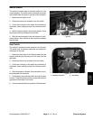
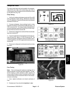
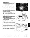
4. Check resistance of the sender with a multimeter.
Resistance with the float in the full position should be
27.5 to 39.5 ohms. Resistance with the float in the empty
position should be 240 to 260 ohms.
Figure 16
FULL POSITION
EMPTY POSITION
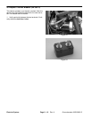
Fuel Gauge
The fuel gauge can be tested using a new gauge as a
substitute or by the use of a DC voltage source and a
variable resistance box.
Note: Before taking small resistance readings with a
digital multimeter, short test leads together. The meter
will display a small resistance value. This internal resis-
tance of the meter and test leads should be subtract
from the measured value of the component.
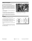
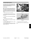
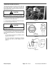
1. Connect the fuel gauge to the variable resistance
and DC voltage source (Fig. 17).
2. Adjust resistance until the gauge needle points to
following test points on the gauge (Fig. 17):
A. The left edge of the red area (empty); the resis-
tance setting should be from 235 to 245 ohms.
B. The middle of the green area (half); the resis-
tance setting should be from 98 to 108 ohms.
Figure 17
S
I
G
+
–
14 VDC
EMPTY FULLHALF
VARIABLE
RESISTANCE
C. The right edge of the green area (full); the resis-
tance setting should be from 30.5 to 40.0 ohms.
3. Disconnect the voltage source, gauge, and variable
resistance.
Electrical System
Page 6 – 14
Rev. A
Groundsmaster 3000/3000–D