


Component Identification and Testing
For accurate resistance and/or continuity checks, elec-
trically disconnect the component being tested from the
circuit (e.g. unplug the ignition switch connector before
doing a continuity check).
CAUTION
When testing electrical components for continu-
ity with a multimeter (ohms setting), make sure
that power to the circuit has been disconnected.
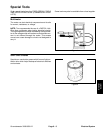
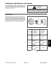
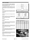
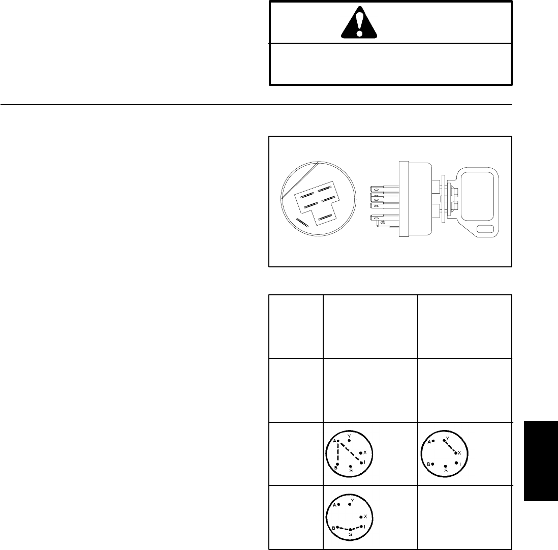
Ignition Switch
The ignition (key) switch has three positions (OFF,
START and RUN). The terminals are marked as shown.
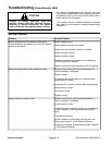
The circuitry of the ignition switch is shown in the chart.
With the use of a continuity tester, the switch functions
may be tested to determine whether all circuits are being
completed while the key is moved to each position.
T OOR
A
B
I
X
S
Y
Figure 4
POSITION
CONTINUITY
AMONG
TERMINALS
OTHER
CIRCUITS
MADE
1. OFF NONE NONE
2. RUN
3.
B+I+A X+Y
B+I+S NONESTART
Figure 5
Groundsmaster 3000/3000–D
Page 6 – 9
Electrical System
Electrical
System