


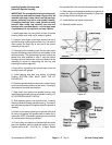
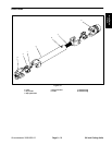


Installing Spindle, Bearings and
Seals Into Spindle Housing
IMPORTANT: If a new spindle housing is being used,
new bearings and matched snap ring set must be
installed; see step 1 below. Never use old bearings,
spacer, and snap ring with a new spindle housing.
If installing bearings into a used spindle housing
that still has a snap ring installed, use only new
bearings with cups and spacer – not the large snap
ring because it is not required; see step 2 below.
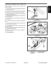
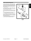
1. Install large snap ring into groove in bore of spindle
housing. Make sure snap ring is seated in groove.
2. Using an arbor press, push large spacer into top of
spindle housing; tightly against snap ring. The spacer
must contact the snap ring to be sure of the correct
assembly of the parts.
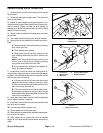
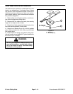
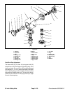
3. Thoroughly oil the bearing cups. Use an arbor press
to push the bearing cups into the top and bottom of the
spindle housing. The top bearing cup must contact the
spacer that was installed in step 2, and the bottom
bearing cup must contact the snap ring. Make that the
assembly is correct by supporting the first cup and
pressing the second against it.
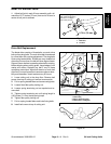
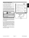
4. Apply a film of grease on lips of both seals. Pack the
bearing cones with grease.
5. Install bearing and seal into bottom of spindle
housing. BOTTOM SEAL MUST HAVE THE LIP
FACING OUT.
6. Check the spindle shaft to make sure it is free of burrs
and nicks that could possibly cut the seals. Thoroughly
lubricate both the shaft and seal lips.
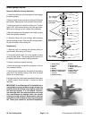
7. Slide small, thick spacer into spindle housing, then
install bearing and seal into top of spindle housing. LIP
OF UPPER SEAL MUST FACE IN.
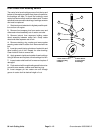
8. Slide bearing spacer onto spindle shaft. Carefully
slide spindle shaft through spindle housing. The bottom
seal and bearing spacer fit together when the spindle is
installed.
9. Attach a hand pump grease gun to grease fitting and
fill cavity with grease until grease starts to come out of
lower seal. NOTE: Pneumatic grease guns can produce
air pockets when filling large cavities.
10. Push pulley onto splines of spindle shaft and retain
the parts together with the large flat washer and nut.
Tighten the nut to 85 – 110 ft–lb (12 – 15 Kgm). Rotate
the spindle shaft to be sure that the shaft rotates freely.
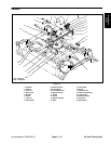
11. Slide pulley end of spindle assembly through hole in
cutting unit. Mount the spindle assembly in place with
the carriage bolts and flange nuts.
12. Install the belt and adjust belt tension.
13. Reinstall the belt covers.
Figure 28
Figure 29
Figure 30
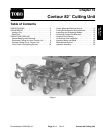
84 inch
Cutting Units
Groundsmaster 3000/3000–D
Page 9 – 17
Rev. A
84 inch Cutting Units