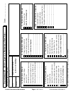
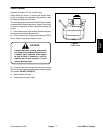
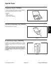
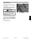
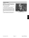
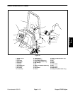
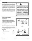
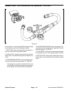
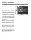
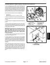
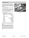
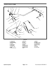
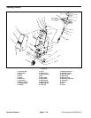
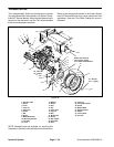
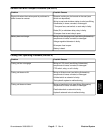
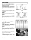
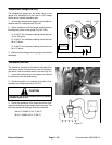
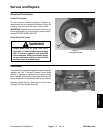
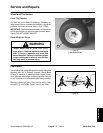
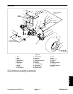
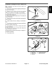
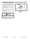
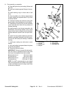
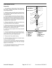
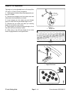
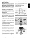
Coolant Level Sensor (GM 3000–D)
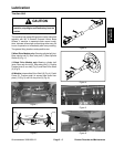
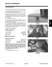
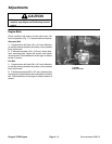
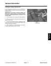
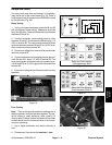
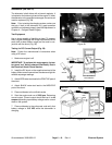
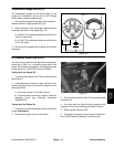
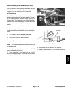
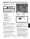
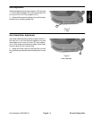
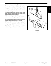
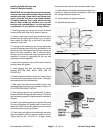
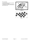
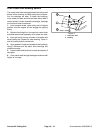
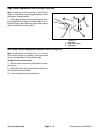
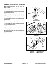
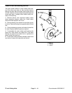
The sensor is located on the degassing box, which is on
the upper left end of the engine. It energizes a red warn-
ing light when coolant level in the degassing box and ra-
diator is to low (Fig. 44).
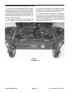
1. Make sure engine is OFF. Remove start relay from
the control center.
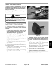
DANGER
Make sure engine and cooling system have
cooled down prior to checking coolant system
levels. Possible steam burns may occur when re-
moving the pressure plug.
2. Make sure cooling system is full (see Check Cooling
System in Chapter 4 – Peugeot Diesel Engine).
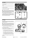
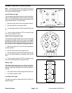
3. Disconnect connector from the sensor. Verify cir-
cuitry to the sensor at the connector using a jumper and
multimeter.
A. Place ignition switch in RUN. Jumper from the
pin for the tan wire to chassis ground, the red warn-
ing light should come on. Turn switch OFF.
B. Hold ignition switch in START. Battery voltage
from the pin for the white wire to chassis ground
should be indicated. Turn switch OFF.
C. Check continuity (1 ohm or less) from the pin for
the black wire to chassis ground..
D. Replace light bulb or correct any problem circuit-
ry if necessary.
4. Reconnect connector to the sensor. Test sensor us-
ing the following steps:
A. Place ignition switch in RUN. The red warning
light should be off. Turn switch OFF.
B. Hold ignition switch in START. The red warning
light should be off. Turn switch OFF.
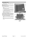
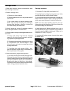
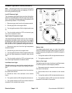
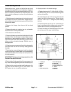
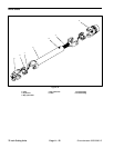
SENSOR
PRESSURE
DEGASSING
PLUG
BOX
CONNECTOR
Figure 44
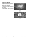
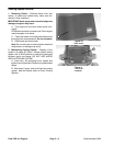
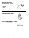
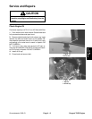
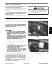
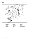
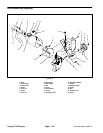
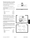
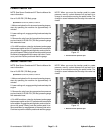
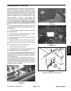
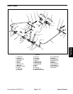
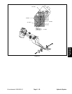
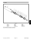
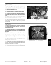
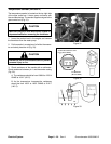
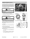
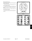
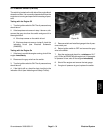
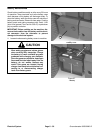
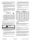
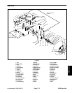
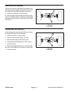
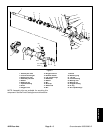
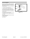
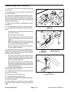
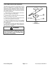
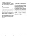
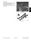
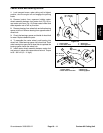
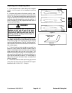
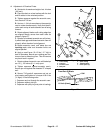
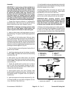
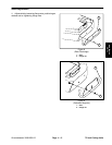
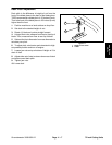
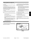
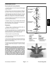
ELECTRODES
Figure 45
5. Disconnect connector from the sensor. Unscrew
sensor from box and dry electrodes. Reconnect connec-
tor to sensor. Test sensor using the following steps (Fig.
45):
A. Place ignition switch in RUN. The red warning
light should come on. Turn switch OFF.
B. Hold ignition switch in START. The red warning
light should come on. Turn switch OFF.
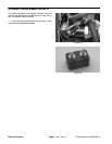
6. Reinstall start relay to the control center.
7. Replace sensor with new one if necessary.
8. Disconnect connector from sensor. Install sensor to
box. Reconnect connector to sensor.
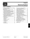
Electrical
System
Groundsmaster 3000/3000–D
Page 6 – 25
Electrical System