


Assembly
IMPORTANT: If new bearings will be installed into a
used spindle housing that has the original large
snap ring installed, discard the snap ring that came
with the new bearings because it is not necessary
to replace the original snap ring. However, new
bearings with their matched spacer set and snap
ring must always be installed when the spindle
housing is being replaced. Replacement bearings
are sold only with a matched snap ring and spacer
set. These parts cannot be purchased separately.
1. If large snap ring was removed, or if replacing the
spindle housing, install snap ring into spindle housing
groove. Make sure snap ring is seated in groove.
IMPORTANT: If bearings are being replaced, make
sure to use the large spacer, inside spacer, and
spacer ring that are included in new bearing set.
2. Using an arbor press, push large spacer into top of
spindle housing. The spacer should fit tightly against the
snap ring.
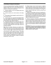
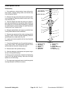
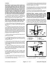
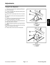
3. Thoroughly oil the bearing cups. Using an arbor
press, push the bearing cups into the top and bottom of
the spindle housing. The top bearing cup must contact
the spacer previously installed, and the bottom bearing
cup must contact the snap ring. Make sure that the as-
sembly is correct by supporting the first bearing cup and
pressing the second against it (Fig 32).
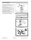
4. Pack the bearing cones with grease. Apply a film of
grease on lips of seals.
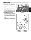
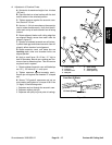
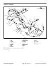
5. Install lower bearing and seal into bottom of spindle
housing. Note: The bottom seal must have the lip facing
out (down) (Fig. 33).
6. Slide spacer ring and inside spacer into spindle
housing, then install upper bearing and seal into top of
housing. Note: The upper seal must have the lip facing
out (up) (Fig. 33).
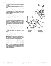
7. Inspect the spindle shaft to make sure it is free of
burrs or nicks that could possibly damage the seals.
Also, make sure that lubrication hole in shaft is clean.
Lubricate the shaft with grease.
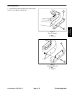
8. Install spindle spacer onto shaft. Carefully slide
spindle shaft through spindle housing. The bottom seal
and spindle spacer fit together when the spindle is
installed fully.
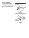
9. Install seal spacer with chamfer side down (Fig. 32).
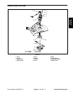
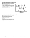
11. Install spindle housing and spindle plate to deck with
cap screws and lock nuts. Notches on housing and plate
should be aligned to front of deck.
12.Install cutting blade, anti–scalp cup and bolt (see
Cutting Blade Removal and Installation). Tighten blade
bolt from 85 to 110 ft–lb (115 to 149 N–m).
13.Position O–ring to top of spindle housing. Install hy-
draulic motor to the cutting unit with two cap screws.
IMPORTANT: When greasing spindles, grease
passes into the center of the shaft and out to fill the
bearing cavity of the housing. If grease does not
come out of lower seal when greasing, check lu-
brication hole in spindle shaft for obstruction.
14.Attach a hand pump grease gun to either grease fit-
ting and fill housing cavity with grease until grease starts
to come out of lower seal. NOTE: Pneumatic grease
guns can produce air pockets when filling large cavities.
1
2
3
4
5
6
PRESS
Figure 32
1. Bearing cups 4. Arbor press
2. Large snap ring 5. Support
3. Large spacer 6. Arbor press base
1
2
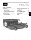
Contour 82
Cutting Unit
10.Thread spindle nut onto shaft and tighten nut from
Figure 33
131 to 159 ft–lb (178 to 216 N–m).
1. Bottom seal installation 2. Upper seal installation
Groundsmaster 3000/3000–D
Page 10 – 21
Rev. C
Contour 82 Cutting Unit