


Blade Spindle Service
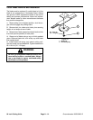
Removing Spindle Housing Assembly
1. Lower the cutting unit, shut the engine off and engage
the parking brake.
2. Remove deck covers from top of cutting unit. Release
belt tension. Remove belt from spindle to be serviced.
3. Start the engine and raise the cutting unit. Turn the
engine OFF and remove the key from the key switch.
Block up the cutting unit so it cannot fall accidentally.
4. Remove blade screw, flat washer, anti–scalp cup and
blade from spindle assembly.
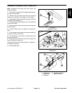
5. Remove flange nuts and carriage bolts securing
spindle housing to deck. Slide spindle housing assem-
bly out the bottom of the cutting unit.
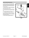
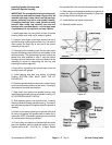
Disassembly
1. Remove lock nut retaining the spindle pulley on
spindle shaft. Slide pulley off of shaft.
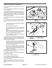
2. Press the spindle shaft out of the spindle housing
using an arbor press. The bearing spacer remains on
the spindle shaft as the shaft is being removed.
3. Remove seals from spindle housing.
4. Allow the bearings and small thick spacer to fall out
of the spindle housing.
5. Using a punch and hammer, drive both of the bearing
cups out of the spindle housing. Also drive the large
spacer out of the housing.
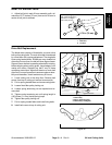
6. A large snap ring is still inside the spindle housing and
it should remain there because it cannot be easily
removed.
IMPORTANT: If new bearings will be installed into a
used spindle housing that has the original snap ring
installed, discard the large snap ring that came with
the bearings because it is not needed. However,
new bearings with their matched spacer and snap
ring must always be installed when the spindle
housing is being replaced. Replacement bearings
are sold only with a matched snap ring and spacer
set. These parts cannot be purchased separately.
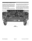
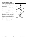
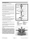
(12 – 15 Kgm)
(12 – 15 Kgm)
Install seal with
lip facing IN
Install seal with
lip facing OUT
85 – 110 ft–lb
85 – 110 ft–lb
1
2
3
4
6
7
8
15
9
5
4
10
11
12
13
14
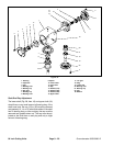
Figure 26
1. Grease fitting 9. Screw
2. Lock nut 10. Spindle shaft
3. Pulley 11. Spindle shaft spacer
4. Oil seal 12. Blade
5. Spacer and bearing assy 13. Anti–scalp cup
6. Spacers – matched set 14. Blade screw
7. Lock nut 15. Flat washer
8. Spindle housing
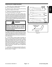
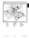
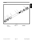
Figure 27
84 inch Cutting Units
Page 9 – 16
Groundsmaster 3000/3000–D