


Wheel Bearing Service
Disassemble, clean, repack and adjust the rear wheel
bearings after each 800 hours of operation. Use No. 2
general purpose lithium base grease containing E.P. ad-
ditive. If operating conditions are extremely dusty and
dirty, it may be necessary to perform this maintenance
more often.
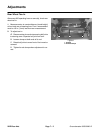
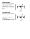
1. Slightly loosen the wheel lug nuts. Jack up the rear of
the machine until the tire is off the floor. Support the ma-
chine with jack stands or blocks to prevent it from falling.
Remove the wheel.
2. Remove the hubcap from the end of the wheel
spindle.
3. Remove the cotter pin, retainer, jam nut, and washer.
Slide the hub off of the spindle shaft.
4. Pull the seal out of the hub.
5. Remove the bearing cones from both sides of the hub
assembly. Clean the bearings in solvent. Make sure the
bearings are in good operating condition. Clean the in-
side of the wheel hub. Check the bearing cups for wear,
pitting or other noticeable damage. Replace worn or
damaged parts.
6. If bearing cups were removed from the hub assembly,
press new ones into the hub until they seat against the
shoulder.
7. Pack bearing cones with grease. Install one bearing
cone into the cup on inboard side of the hub assembly.
Lubricate the inside of the new lip seal and press it into
the hub assembly.
IMPORTANT: The lip seal must be pressed in so it is
flush with the end of the hub.
8. Pack inside of hub assembly with some grease (not
full). Install remaining bearing cone into the bearing cup.
9. Slide the hub onto the spindle shaft and secure it in
place with the tab washer, jam nut, and retainer. DO
NOT tighten the nut or install the cotter pin.
10. Adjust preload on the wheel bearings.
A. Tighten the jam nut to 75 – 80 in–lb (86 – 270 Kg–
cm) while turning the hub to seat the bearings and
remove all end play.
B. Loosen the jam nut until it is away from the tab
washer and the hub has end play. Tighten the jam
nut to 15 – 20 in–lb (17 – 23 Kg–cm) while rotating
the hub.
C. Put the retainer over the jam nut. If the cotter pin
hole is not aligned with a retainer slot, remove the
retainer and re–orient it until alignment occurs.
D. Insert the cotter pin. Bend both legs of the cotter
pin and tap out of the way. Install the cap.
8
7
9
10
11
6
12
1
2
5
3
4
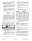
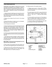
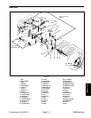
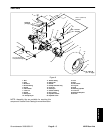
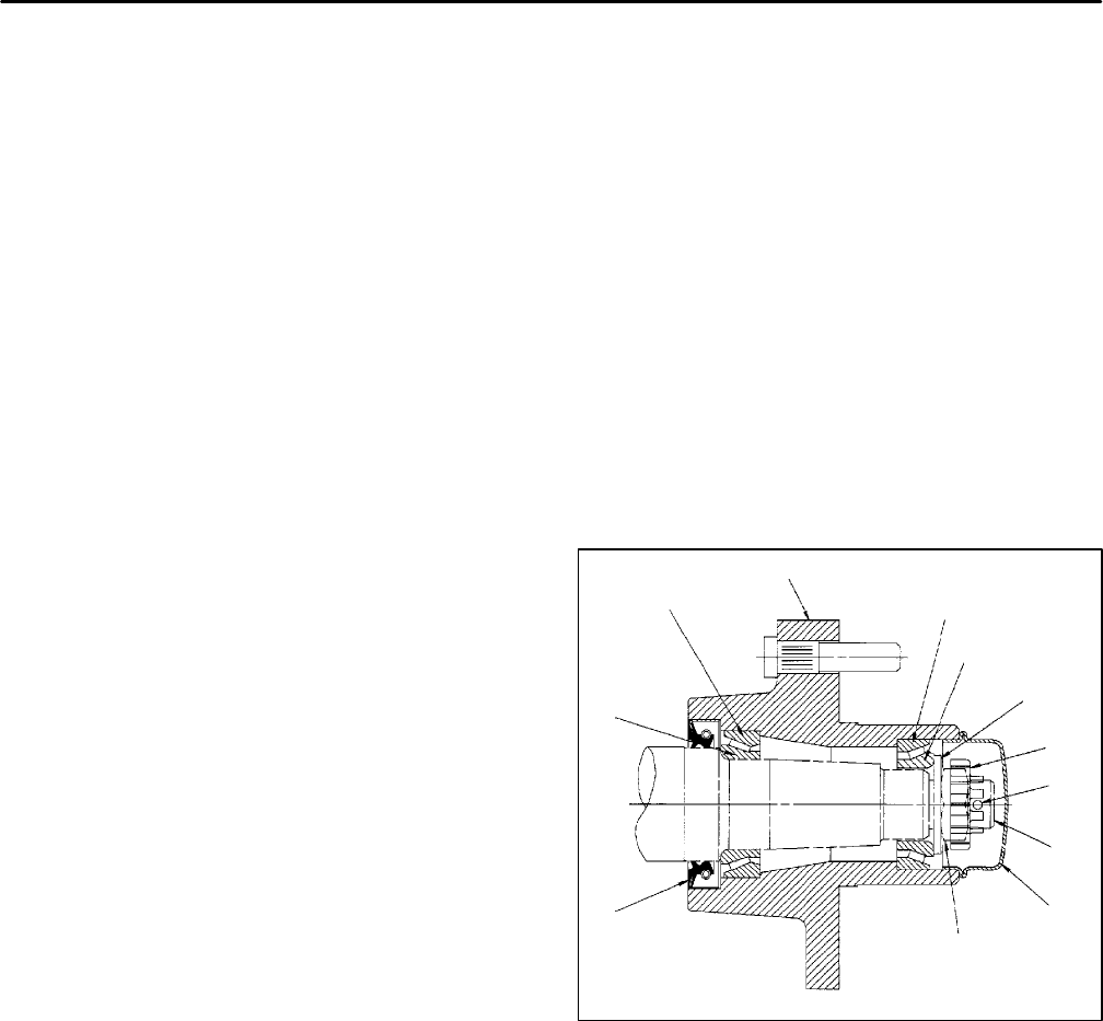
Figure 4
1. Cotter pin 7. Inner bearing cup
2. Spindle 8. Wheel hub
3. Cap 9. Outer bearing cup
4. Washer 10. Outer bearing cone
5. Seal 11. Washer
6. Inner bearing cone 12. Retainer
13. Jam nut
2WD Rear Axle
Page 7 – 4
Groundsmaster 3000/3000–D