


Connect Cutting Unit to Traction Unit
1. Center traction unit in front of cutting unit on any flat
hard surface.
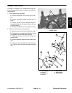
2. Raise seat and open needle valve. This allows lift
arms to float freely.
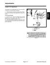
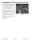
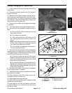
3. Adjust lift arms heights making sure that the ma-
chined surface on top of each traction unit lift arm is par-
allel to ground (Fig. 12). (Raise or lower lift arm casting
by pushing up or down from behind the front tires or us-
ing wrench in front of traction unit)
4. Check for dirt and debris on mating parts and clean
as required.
5. Turn castor wheels so they point straight forward.
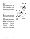
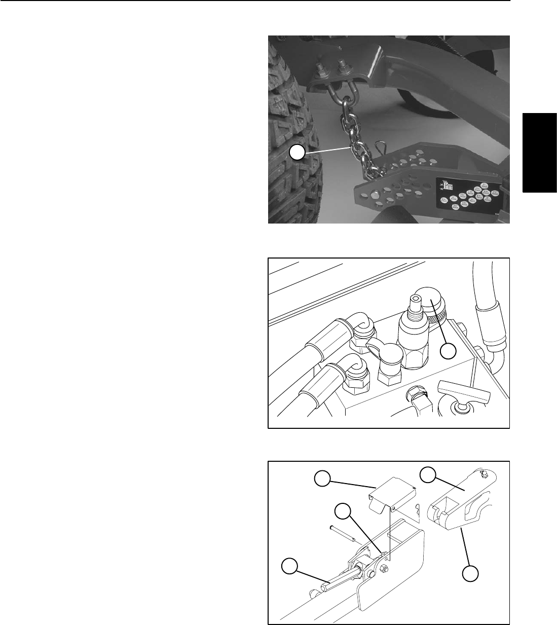
6. Secure first lift arm assembly to traction unit as fol-
lows:
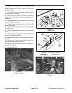
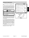
Figure 14
1
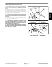
A. Remove hair pin cotter and clevis pin securing
latch cover to lift arm.
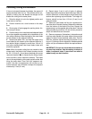
1. Height–of–Cut chain
B. Pivot release lever upward.
C. Slide cutting unit lift arm onto traction unit lift
arm, inserting shaft latch into slot in traction unit
lift arm.
Note: If latch does not fall into slot in traction unit
lift arm, raise or lower lift arm casting by pushing
up or down from behind the front tires.
D. Pivot release lever downward and tighten se-
curely by rotating clockwise.
7. Install other lift arm on traction unit by rotating deck
towards traction unit, aligning lift arm to traction unit arm
and repeating step 5. If latch does not fall into slot in trac-
tion unit lift arm the arms are not lined up.
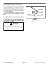
1
Figure 15
A. If lift arms on traction unit are not at the correct
1. Needle Valve
height for deck arms to slide on, push up or down
on lift arm castings from behind the front tires until
deck arm line up and slide on.
B. If lift arms on deck do not line up side to side.
Rotate castor wheels side ways so deck moves
side to side easier. Move deck side to side until lift
arms line up and slide on.
8. Move deck from side to side to check for tightness
and re–tighten latches, if required.
9. Install latch covers to lift arms and secure with clevis
pins and hair pin cotters.
10. Clean hydraulic coupler with a clean rag and con-
nect hydraulic lines to traction unit.
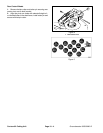
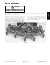
Figure 16
1
2
3
5
4
11. Close needle valve and lower seat.
1. Latch Cover 4. Traction Unit Lift Arm
12. Start traction unit and raise deck to highest possible
2. Release Lever 5. Machined Surface
3. Shaft latch
position and turn off engine.
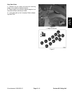
13. Align height–of–cut chain on chamber 3 with hole
for desired height–of–cut, install clevis pin and secure
with hair pin cotter.
Groundsmaster 3000/3000–D
Page 10 – 9
Contour 82 Cutting Unit
Contour 82
Cutting Unit