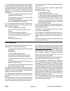
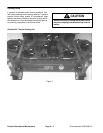
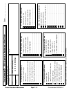
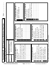
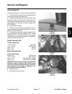
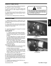
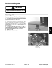
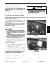
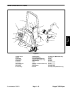
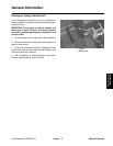
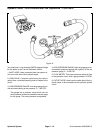
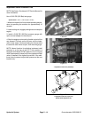
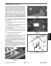
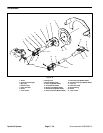
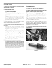
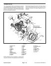
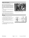
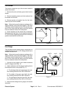
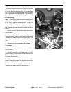
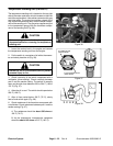
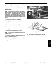
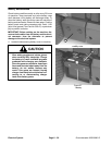
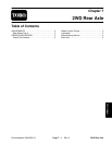
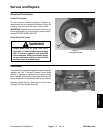
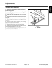
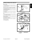
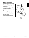
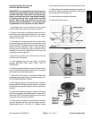
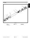
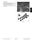
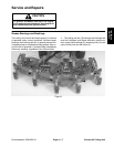
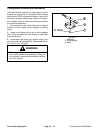
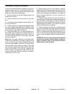
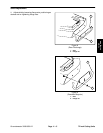
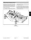
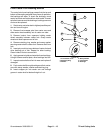
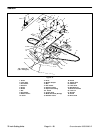
Relays and Fuses
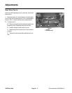
The relays and fuses and are located in the compart-
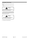
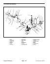
ment that is rear of the control panel (Fig. 18). There is
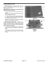
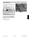
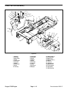
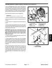
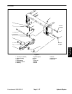
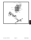
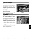
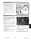
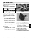
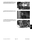
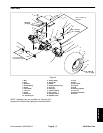
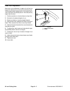
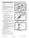
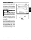
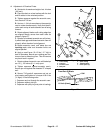
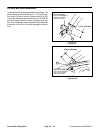
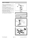
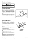
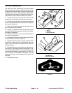
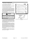
an 80 ampere fuse (50 ampere on the GM 3000) located
by the alternator (Fig. 22).
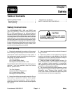
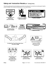
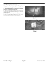
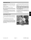
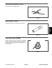
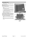
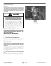
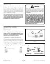
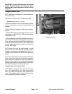
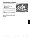
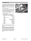
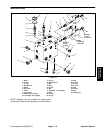
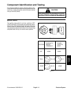
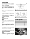
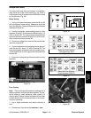
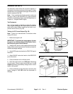
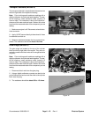
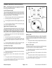
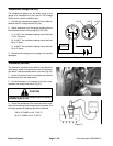
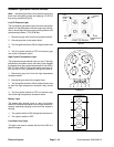
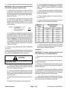
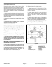
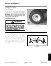
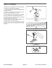
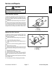
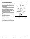
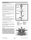
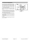
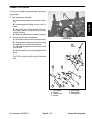
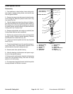
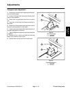
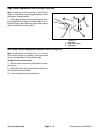
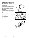
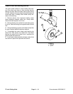
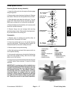
Relay Testing
1. Verify coil resistance between terminals 86 and 85
with a multimeter (ohms setting). Resistance should be
from 75 to 95 ohms. There should be continuity between
terminals 87A and 30.
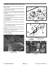
2. Connect multimeter (ohms setting) leads to relay
‘
87
30
87A
86
85
30 85 86 87 87A
Figure 19
terminals 30 and 87. Ground terminal 86 and apply +12
VDC to terminal 85. The relay should make and break
continuity between terminals 30 and 87 as 12 VDC is ap-
plied and removed from terminal 85.
3. Disconnect voltage from terminal 85 and multimeter
lead from terminal 87.
4. Connect multimeter (ohms setting) lead to relay ter-
minal 30 and 87A. Apply +12 VDC to terminal 85. The
relay should break and make continuity between termi-
nals 30 and 87A as 12 VDC is applied and removed from
terminal 85.
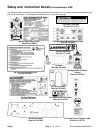
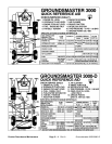
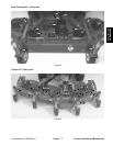
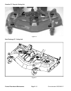
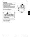
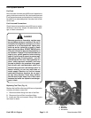
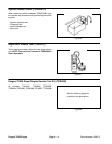
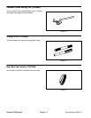
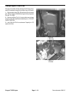
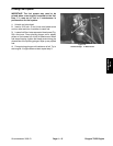
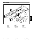
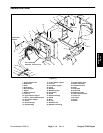
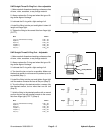
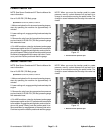
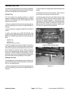
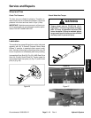
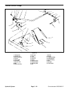
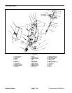
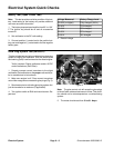
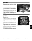
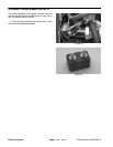
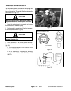
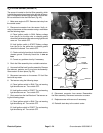
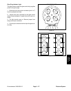
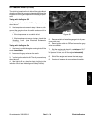
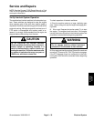
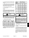
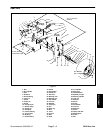
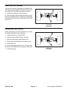
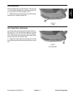
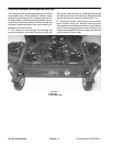
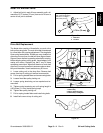
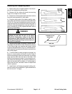
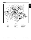
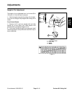
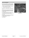
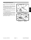
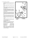
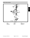
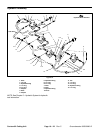
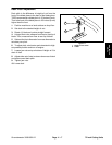
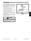
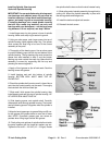
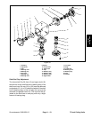
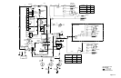
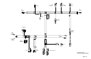
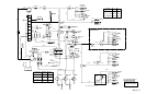
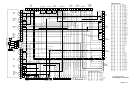
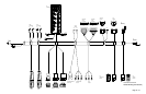
Relay and Fuse Location
(Groundsmaster 3000)
Figure 20
5. Disconnect voltage and multimeter leads from relay
terminals.
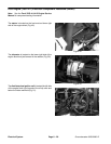
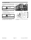
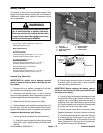
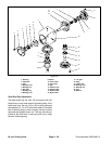
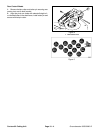
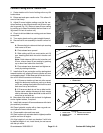
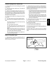
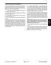
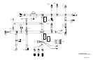
GM 3000–D SHOWN
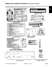
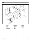
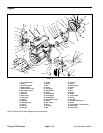
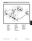
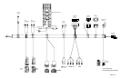
Figure 21
Figure 18
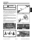
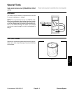
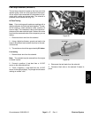
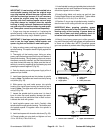
Fuse Testing
Note: Prior to taking small resistance readings with a
digital multimeter, short the test leads together. The me-
ter will display a small resistance value (usually 0.5
ohms or less). Subtract internal resistance of the meter
and test leads from the measured value of the compo-
nent you are testing.
1. Use a digital multimeter and check continuity of
fuse.
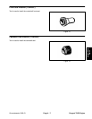
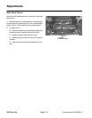
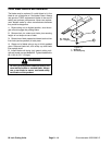
Figure 22
2. Resistance of fuse should be less than 1 ohm.
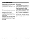
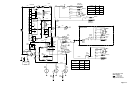
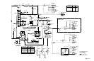
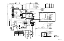
Relay and Fuse Location
(Groundsmaster 3000–D)
Groundsmaster 3000/3000–D
Page 6 – 15
Electrical System
Electrical
System