


Blade Spindle Service
Disassembly
1. Park machine on a level surface, lower cutting units,
stop engine, engage parking brake, and remove key
from the ignition switch.
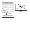
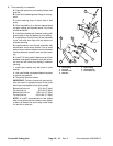
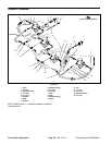
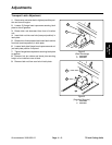
2. Remove two cap screws that secure hydraulic motor
to the cutting unit. Remove hydraulic motor and O–ring
from deck (Fig. 30).
3. Start the engine and raise the cutting unit. Stop en-
gine and remove key from the ignition switch. Block up
the cutting unit so it cannot fall accidentally. If required
for easier service, remove cutting unit (see Disconnect
Cutting Unit From Traction Unit).
4. Remove cutting blade, anti–scalp cup and bolt (see
Cutting Blade Removal and Installation).
5. Remove cap screws and lock nuts securing spindle
housing to deck. Remove spindle assembly. Remove
spindle plate from under deck (Fig. 30).
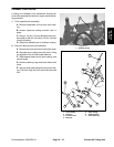
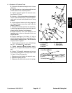
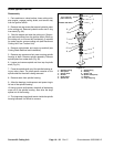
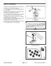
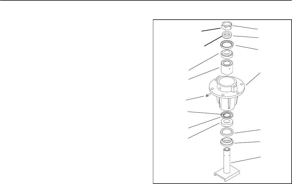
6. Loosen and remove spindle nut from top of spindle
shaft (Fig. 31).
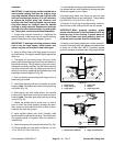
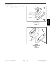
7. Press the spindle shaft out of the spindle housing us-
ing an arbor press. The shaft spacer remains on the
spindle shaft as the shaft is being removed.
8. Remove seals from spindle housing.
9. Allow the bearings, inside spacer and spacer ring to
fall out of the spindle housing.
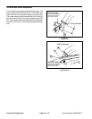
10.Using a punch and hammer, drive both of the bearing
cups out of the spindle housing. Also drive the large
spacer out of the housing.
11. The large snap ring should remain inside the spindle
housing because it is difficult to remove.
6
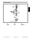
131 to 159 ft–lb
(178 to 216 N–m)
2
Chamfer side down
4
8
1
10
7
9
12
4
8
5
3
Figure 31
1. Spindle housing
7. Grease fitting
2. Seal spacer
8. Bearing
3. Spindle shaft
9. Spacer ring
4. Oil seal
10. Spacer set (2 piece)
5. Shaft spacer
11. Bearing
6. Spindle nut
12. Large snap ring
Contour 82 Cutting Unit
Page 10 – 20
Rev. C
Groundsmaster 3000/3000–D