


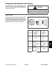
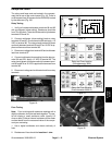
DIODE
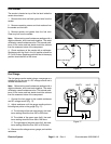
Diode Circuit Boards
Each circuit board contains four diodes. The diodes are
D2
used for circuit protection from inductive voltage spikes,
battery charging indication, and for safety circuit logic.
D4
D6
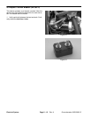
Diodes D4 and D8 are not used.
D8
On the GM 3000 wiring diagram, the diode circuit cards
D3
a designated P3 and P5. On the GM 3000–D wiring dia-
D7
grams, the diode circuit cards are designated P7 and
D1
P5.
D5
Diode D1
Directs current flow from the deck capacitor to the deck
relay when the seat relay is de–energized to provide a
1 second delay.
A B C D E F G H
DIAGRAM
Figure 6
Diode D2
Provides current flow logic for the charging circuit light.
Diode D3
Prevents a negative spike from damaging the PTO
switch by allowing a ground path for the PTO relay and
PTO coil when they de–energize.
Diode D4
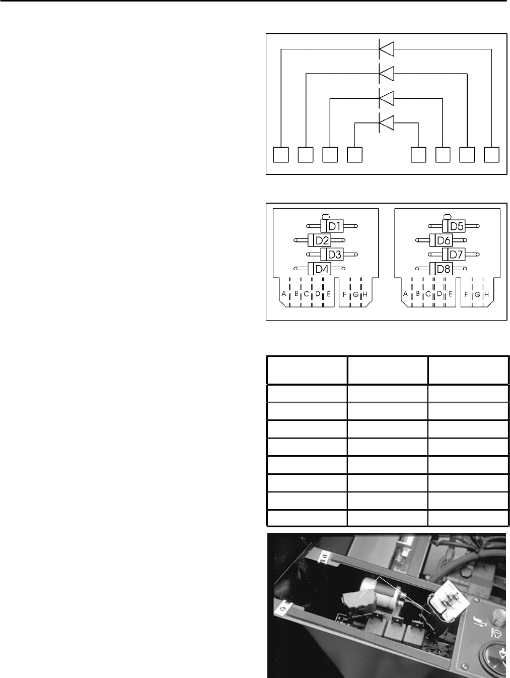
DIODE
P3 or P7 P5
CIRCUIT BOARDS
Figure 7
This component is not used.
Diode D5
Prevents a negative spike from damaging the Lift/Xbal
switch by allowing a ground path for the Lift/Xbal sole-
noid (SV1) when it de–energizes.
Diode D6
Prevents a negative spike from damaging the Cruise
switch by allowing a ground path for the Cruise relay and
Cruise coil when they de–energize.
Diode D7
Prevents a negative spike from damaging the Transport
switch by allowing a ground path for the Transport relay
and Transport coil when they de–energize.
Diode D8
Prevents a negative spike from damaging the Float/
Hold switch by allowing a ground path for the Float/Hold
solenoid (SV2) when it de–energizes.
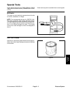
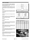
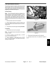
Testing
The diodes can be individually tested using a digital
multimeter (ohms setting) and the table to the right.
Red Lead (+)
on Terminal
Black Lead (–)
on Terminal
Continuity
H A YES
A H NO
G B YES
B G NO
F C YES
C F NO
E D YES
D E NO
DIODE CIRCUIT BOARD
Figure 8
Electrical System
Page 6 – 10
Groundsmaster 3000/3000–D