


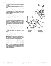
3. Pivot assembly re–assemble.
A. Press ball joints into pivot casting. Bottom ball
joint first.
B. Insert and orientate grease fittings to face up-
ward.
C. Install retaining rings on back side of ball
joints.
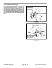
D. Clean any debris, oil, or dirt from tapered joints
on span casting and tapered sleeve. Any nicks
should be filed off.
E. Install pivot casting into chamber housing with
spacer plate on top and bottom of pivot casting.
F. Install pilot pin into 5/8 inch (16 mm) diameter
“pivot” hole and drive flush with top surface of
chamber housing.
G. Install eccentric cam through assembly with
identification mark facing forward. Use a small
amount of anti–seize compound on the diameter
interface between eccentric cam and pivot cast-
ing.
H. Install 7/16 inch grade 8 fasteners (and thick
washers) and tighten assembly such that eccen-
tric cam can still rotate pivot casting in chamber
housing.
I. Install span casting over ball joints in pivot
casting.
J. Use a soft mallet, tap tapered sleeve into place
in top ball joint position.
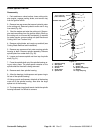
K. Torque ball joints as follows:
IMPORTANT: Failure to torque ball joints as fol-
lows can result in premature wear of ball joints
due to pre–load applied to ball joint sockets.
Bottom ball joint nut 50 ft–lbs (7 Kgm)
Top ball joint nut 50 ft–lbs (7 Kgm)
Bottom ball joint nut 125 ft–lbs (17 Kgm)
Top ball joint nut 125 ft–lbs. (17 Kgm)
NOTE: It is NOT recommended to use slotted
nuts on ball joints due to the need to over tighten
or back–off slotted nuts and to align cross holes
for use with a cotter pin.
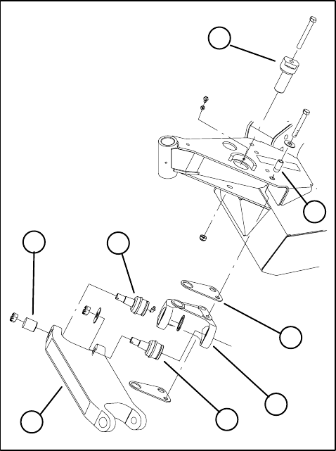
1
2
3
4
4
5
6
7
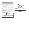
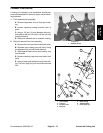
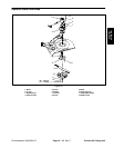
Figure 25
1. Pivot casting 5. Span casting
2. Pivot pin 6. Tapered sleeve
3. Eccentric cam 7. Pivot spacer (2)
4. Ball joint
Contour 82 Cutting Unit
Page 10 – 16 Rev. A
Groundsmaster 3000/3000–D