


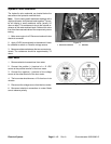
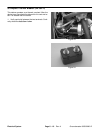
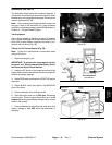
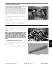
Alternator (GM 3000–D)
The alternator is belt driven with a internal regulator. It
is located on the bottom right end of the engine. If either
the alternator or the regulator is damaged, the entire unit
must be replaced (Fig. 28).
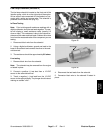
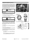
Note: Prior to testing the charging system, make sure
the poly V–belt to the alternator is in good operation
condition and adjusted properly (see Belt Adjustment in
Chapter 4 – Peugeot Diesel Engine).
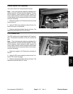
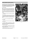
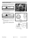
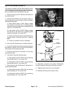
Test Equipment
Use a shunt capable of handling at least 70 ampere.
Also, a digital multimeter with a high impedance millivolt
scale (with at least 300mv range) can be used in con-
junction with the shunt (Fig. 29).
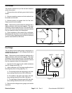
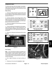
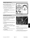
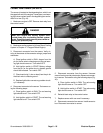
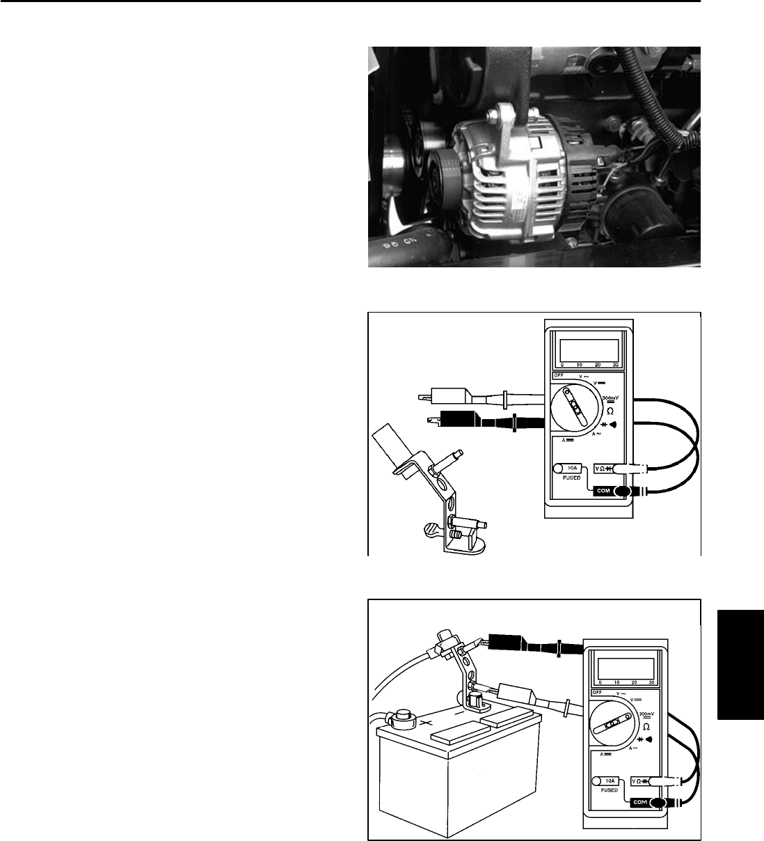
Testing for DC Current Output (Fig. 30)
Note: Follow the manufacturer’s instructions when
using a DC shunt.
1. Make sure engine is off.
IMPORTANT: To perform this test properly, the bat-
tery must “not” be fully charged. See Battery Test in
the Electrical Quick Checks section.
2. Install the DC shunt on the negative terminal of the
battery. Make sure all connections are clean and tight for
reliable amperage readings.
3. Attach RED meter test lead to the POSITIVE post of
the shunt.
4. Attach BLACK meter test lead to the NEGATIVE
post of the shunt.
5. Place multimeter to the millivolts scale.
6. Start the engine and run at 2000 rpm. Determine
current output. Current output should be from 1 to 45
ampere depending upon battery voltage and/or current
draw on the system.
7. Place multimeter to the volts scale, and verify that
battery voltage is 13.5 VDC while the alternatoer is
charging.
Figure 28
HIGH IMPEDENCE
SHUNT
MULTIMETER
Figure 29
NEGATIVE
BLACK
CABLE
LEAD
RED
LEAD
BATTERY
Electrical
System
Figure 30
Groundsmaster 3000/3000–D
Page 6 – 19 Rev. A
Electrical System