Performance Verification
4-60
AWG510 & AWG520 Service Manual
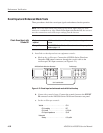
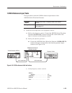
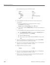
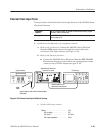
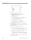
d. Set the function generator (AFG310) controls:
Function . ....................... Square
Mode .......................... Continuous
Parameters ......................
Frequency .................. 10MHz
Amplitude . .................. 2.0V(4Vintoopen circuit)
Offset . ..................... 0V
Output ......................... On
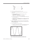
2. Set the AWG500–Series Waveform Generator controls and select the
waveform file:
a. Initialize the AWG500–Series Waveform Generator controls:
Push UTILITY (front–panel)!
System (bottom)!Factory Reset (side)!OK (side).
b. Select the file: Load the MODE.WFM as referring to the procedures on
page 4–15.
c. Set the AWG500–Series Waveform Generator clock reference to external:
H Push HORIZONTAL MENU (front–panel)!Clock Ref (side) so
that the clock reference is set to External.
H Push the Clock side button.
H Enter numeric value of 50M: Push 5, 0, M (SHIFT+7) keys in this
order.
3. Turn on the AWG500–Series Waveform Generator output: Push the RUN
button so that the LED above the RUN button lights.
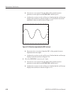
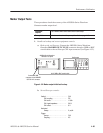
4. Check the clock output frequency with 10.0 MHz reference: Check that the
frequency counter reading is 50.0 MHz "10 kHz.
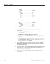
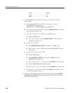
5. Modify the function generator controls:
Frequency ...................... 10.1 MHz
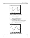
6. Check the clock output frequency with 10.1 MHz reference: Check that the
frequency counter reading is 50.5 MHz "10 kHz.
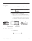
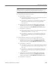
7. End procedure: Turn the function generator output off and disconnect the
function generator and frequency counter.


