Performance Verification
4-50
AWG510 & AWG520 Service Manual
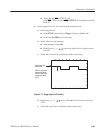
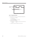
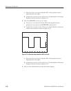
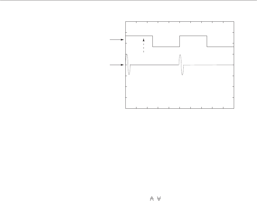
Trigger Signal CH2
(5.35 V level)
CH1
Figure 4-18: Trigger Signal (+5V check2)
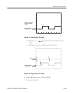
5. Verify the Trigger level accuracy at –5V by following the substeps below:
a. Set the trigger level of AWG500.
H Push Level (side).
H Push –, 5 and ENTER keys in this order.
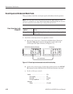
b. Set the offset level of generator.
H Push Cursor, %, &,
, keys as the low level of a pulse to be set
to –4.65V.
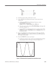
c. Verify that no waveform is displayed on the oscilloscope.


