Performance Verification
4-32
AWG510 & AWG520 Service Manual
Amplitude and Offset Accuracy Tests (Normal Out)
These procedures check the accuracy of the AWG500–Series Waveform
Generator normal waveform outputs; amplitude and offset.
NOTE. The amplitude and offset accuracy checks are structured as a continuous
test. After Check Amplitude Accuracy, the next test uses the control settings from
the last test and uses the next step in the sequence file.
Equipment
required
A 50ĂΩ coaxial cable, a 50ĂΩ precision terminator, a BNC (female)ĆtoĆ
dual banana adapter, and a digital multimeter (DMM).
Prerequisites The instrument must meet the prerequisites listed on page 4-13.
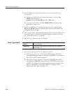
1. Install the test hookup and set test equipment controls:
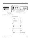
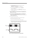
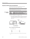
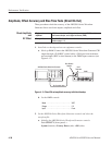
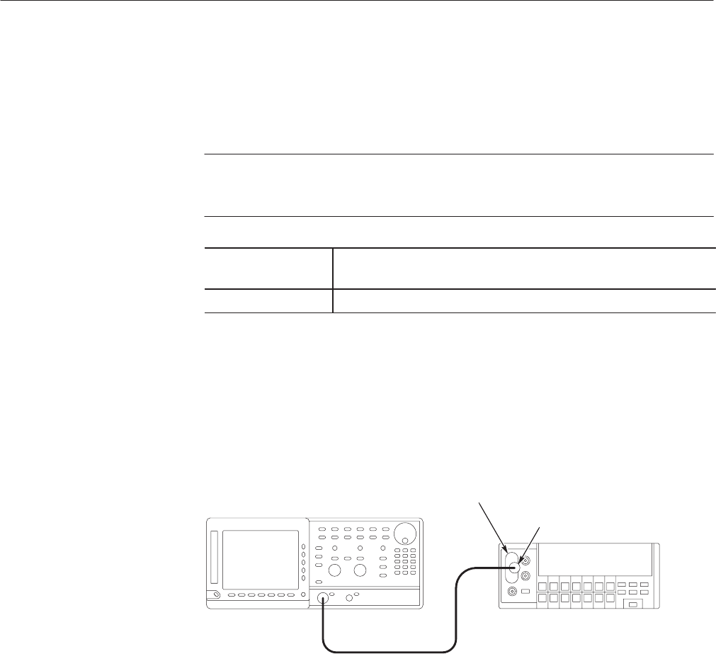
a. Hook up DMM: Connect the AWG500–Series Waveform Generator CH1
output through a 50 Ω BNC coaxial cable, a 50 Ω precision terminator,
and an adapter (BNC-to-dual banana) to the DMM input connector (see
Figure 4–10).
AWG500 Series Waveform Generator
DMM
50 W coaxial cable
Dual Banana
Adapter
50 W
Terminator
Figure 4-10: Amplitude accuracy initial test hookup
b. Set the DMM controls:
Mode . ......................... VDC
Range ......................... Auto
Input .......................... Front
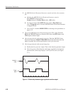
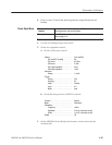
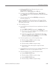
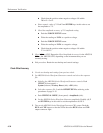
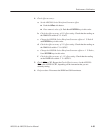
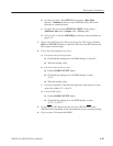
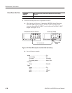
2. Set AWG500–Series Waveform Generator controls and select the sequence
file:
Check Amplitude
Accuracy


