


SECTION 15: REMOVAL AND REPLACEMENT PARTS
51
SECTION 15: REMOVAL AND REPLACEMENT
PARTS
See warnings and notes on Page 43, Section 12
before removing or replacing parts.
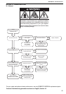
15.1 Burner Components
To remove the burner from the heater:
1. Unplug the burner electrical supply from the
heater.
2. Isolate the fuel supply at the inlet manual valve
and disconnect the inlet fuel pipe.
3. Unscrew the nuts holding the burner mounting
flange to the heater.
4. Remove the burner from the heater, retaining
the gasket for reuse.
For removal of burner components, follow the
manufacturer’s instructions. To refit the burner,
reverse the instructions above. Fit the gasket
between the burner mounting flange and the heater.
Use a new gasket if necessary.
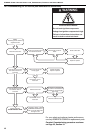
15.2 Direct On-Line Main Fan Starter and
Thermal Overload Unit (3 Ø)
This assembly comprises two parts, the contactor
and the overloads, which may be changed
seperately.
15.2.1 The Contactor
To remove the contactor:
1. Remove the overloads as on Page 51, Section
15.2.2.
2. Remove the line connections to the top of the
contactor (noting the colour code) and the two
coil connections at the top rear of the contactor.
3. Unscrew the fixing screws to remove the con-
tactor from the panel.
4. Reverse these instructions to refit. Check rota-
tion of the fan after working on the contactor.
15.2.2 The Overloads (models 060 to 100)
To remove the overloads:
1. Unscrew the motor connecting wires from their
terminals at the bottom of the assembly. Note
the colour code.
2. Disconnect the overload circuit connections
near the overload reset button.
3. Disconnect the overload fixing and connecting
screws from the bottom of the contactor.
4. Ensure that any replacement overload is of the
correct rating and that it is reset correctly. See
Page 33, Section 10.1.6.
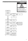
15.3 Control Circuit Fuse (10 or 5 A, 1-1/4" long
sand filled)
The control fuse is removed by grasping the centre
and pulling it out of the spring clips. To replace, push
a new fuse into the spring clips. To replace the
holder, remove the fuse, pull off the two tag
connectors from either end, and then unscrew the
central screw. Reverse these instructions to refit.
15.4 Combination Fan/Limit Thermostat
To gain access to the thermostat:
1. Loosen the cover retaining screw (on top) and
remove cover.
2. Disconnect the electrical connections by push-
ing in with a small screwdriver and pulling out
the wiring. See Page 52, Figure 22.
3. Unscrew the conduit bush and the two screws
and withdraw the unit from the cabinet.
4. Reverse these instructions to refit. See Page
34, Figure 13 to set the new thermostat.
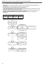
15.5 Main Fan Motor (3 Ø Belt Drive)
1. Disconnect electrical connections at contactor
and overloads. See Page 51, Section 15.2.
2. For Star/Delta starters, there are six wires
between the motor and the starter.
3. Remove the left lower side panel to access the
motor.
4. Unscrew the bolts securing the motor to the
mounting bracket. Lift the motor out.
5. Reverse these instructions to refit, tensioning
the belts as on Page 43, Figure 21 and ensur-
ing the pulleys are aligned.
6. For Star/Delta starters, pay specific attention to
the six motor connections.
15.6 Main Fan Units
Depending on the model of the heater, the main fan
unit will be direct drive (with integral motor) or belt
drive. Models 060-100 are belt drive, double fan
units. All the fans are secured to the base of the
heater by four bolts per fan case, and to the fan tray
by bolts through the outlet flange.
To gain access to the fans:
1. Remove the lower side panels of the heater.
For models 060-100 and High Flow models,
remove the upper side panels of the same side
and the vertical centre bar to allow the fans to
slide out of the cabinet.
2. Disconnect the electrical connections. On
direct drive units, these will be at the terminal
block for single phase and at the contactor for
three phase.
3. Remove the screws. The fan will pull out of the
heater through the side.
4. Reverse these instructions to refit, tensioning
the belts as on Page 43, Figure 21.