


SECTION 10: COMMISSIONING
39
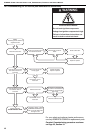
10.7.2 Sequence of Operation
The operating sequence is as follows:
With the external controls on and calling for heat,
the burner fan and electric ignition will switch on.
After a combustion air purge of approximately twelve
seconds, the oil solenoid valve will open and the
burner will fire. After another five seconds, the
electric ignition is turned off and the burner will go
into its normal run position. The photo cell
continuously monitors the safe presence of the
flame. When the temperature control is satisfied, the
control box will turn off all its outputs simultaneously
and return to the rest position for the beginning of
the next sequence.
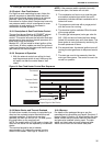
10.7.3 Fault Display Messages
On burner failure, the red LED is permanently
illuminated for a period of approximately 10
seconds, followed by a brief “dark phase”, then one
of the following flash-codes will indicate the cause of
the fault. See Table 1 and Table 2. This indication
will repeat as long as the lockout reset button is not
reset.
Table 1: Fault Display
Table 2: Error Diagnosis
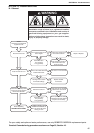
10.7.4 Fault Conditions
If at any stage during normal running the photo
electric cell fails to detect the flame, the control will
switch off and make an instant restart attempt. If the
flame signal is still missing, “lockout” will occur.
If the flame is not detected by the photo cell during a
normal start, there will be no restart attempt and
“lockout” will occur in approximately 17 seconds
after the start.
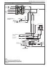
If a flame is detected during the first 12 seconds
(purge), the solenoid valve will not open and the
control will “lockout”. For the control sequence, see
Page 38, Figure 18.
10.7.5 Switching On
Turn on the heater with the external controls. (Heat
ON). If the "Lockout Reset" button is illuminated,
press to reset. The combustion air fan and electric
ignition should work immediately. Vent the burner oil
pump at the same time by loosening the pump vent
port (pump must be running). If the burner goes into
"lockout" before the pump has vented, wait one
minute, then reset the control box and repeat 10.7.5
until all the air has been vented from the pump and
the burner fires.
NOTE: The burner plug and socket may be used to
turn off the burner during commissioning.
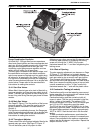
10.7.6 Adjust Burner Oil Pressure
Adjust the burner oil pressure to the value in the
data table for the burner reference letter and burner
manufacturer’s information for details of the burner
oil pump. When completed, turn off burner and
remove test gauge and refit plug.
10.7.7 Set Combustion Air
The combustion air must be set. Measure the
emissions in the flue at a point within one metre from
the outlet of the heater and adjust for the highest
carbon dioxide (CO
2
) levels obtainable, usually 10.5
- 11.0%, while making little or no smoke (smoke
number 0-1). The test must be carried out with all
covers fitted and after the heater has been running
for 15 minutes.
10.7.8 Complete the Commissioning
Test the burner for correct start and stop operation
several times. Check that all safety devices operate
correctly. Inspect the heater for any oil leaks and
repair where necessary.
10.8 Turning Off the Heater (all models)
Set the external controls to the “off” position and the
main burner will stop. The fans will run until they are
stopped automatically by the fan thermostat.
Do not use Electrical Isolator for control of
heater. The Electrical Isolator will switch off the
fan. The heat exchanger could be damaged. The
Warranty will not cover damage to the heat
exchanger if operated improperly.
10.9 External Controls
External controls may include a time switch, room
thermostat and frost thermostat. Operate each
control to ensure that they function correctly. Set the
time switch (if fitted) and room thermostat to the
user’s requirements.
10.10 Instruction to the User
Explain the controls of the heater to the user,
including how to turn it on and off, using the controls
fitted on site.
Give this manual to the user.
Ensure that the user is shown and understands the
importance of maintaining clearances to
combustibles; the user instructions on Page 40,
Section 11 through Page 41, Section 11.4; and all
warnings defined in this manual.
Flash-Code Key Message Flash-Code
Short Pulse l
Long Pulse l
Short Pause .
Long Pause _
Pre-ignition
tv1
l l l l .
Safety Time
tv2
l l .
Delay Time to Valve V2
tv2
l l l .
Running l _
Low Mains Voltage l l l _
Error Message Flash-Code Possible Fault
Lockout l l l l l
Within lockout safety time,
no flame established.
Stray Light l l l l l
Stray light during monitor
phase, detector may be
faulty.
Flash-Code for Manual Lockout
Manual/External
Lockout
l l l l l _ l l l l l