


SECTION 9: WIRING AND ELECTRICAL INFORMATION
23
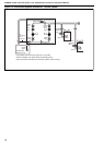
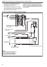
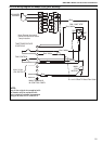
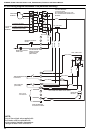
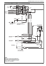
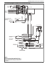
9.6 CCH Wiring Diagram Oil Models 15-30 (horizontal mounting)
Red
1
2
3
4
N
10 A
MAIN TERMINALS
IN CONTROL PANEL
Blue
Blue
Blue
L
L
L
1
2
3
PACKAGED
BURNER
FAN
LIMIT
FAN / LIMIT STAT
Brown
7
8
2
7
R1 COIL 240v
3
1
LOCKOUT SIGNAL
BURNER RUN SIGNAL
LOCKOUT RESET SIGNAL
5
6
REMOTE LOCKOUT
RESET
N
REMOTE LOCKOUT
LAMP 230V
MAIN FAN
MOTOR
OUTPUTS
FROM
BURNER
TIME/TEMPERATURE
CONTROLS
FAN CONTROL
(OPTIONAL)
Red / White
Red / White
Red / White
Red / White
Red / White
Red
Red / White
Red / White
Red / White
Red / White
Red / White
230 V 50 Hz
1 PH SUPPLY
1 mm Ø RED TRI RATED FLEX CABLE
S3 T2 T1 N L1
S3 T2 T1 N L1
OIL BURNER 6-WAY PLUG
FOR BURNERS WITH
SATRONIC CONTROL BOX
(OIL-FIRED)
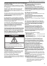
NOTE:
Any of the original wire supplied with
the heater must be replaced with wiring
material having a temperature rating of
at least 105°C and 600 V.