


SECTION 6: FLUE INSTALLATION
13
SECTION 6: FLUE INSTALLATION
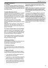
6.1 Flue Installation
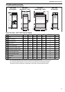
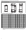
Flues must be correctly sized for the model. See
Page 5, Section 4.1. Flues should be assembled as
on Page 13, Figure 4 and Figure 5 and Page 14,
Figure 6 through Page 14, Figure 9. The joints
between the flue and the roof or wall must be
properly sealed. If the flue passes through a wall or
ceiling of combustible material it must be enclosed
by a sleeve of non-combustible material and be
separated from the sleeve by at least a 25 mm air
gap.
Flues must be adequately supported so that the
heater does not bear the weight of the flue.
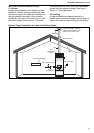
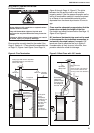
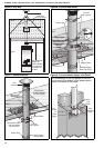
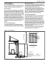
For straight and offset flue termination See Page 13,
Figure 4 and Figure 5.
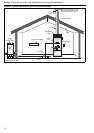
90° bends and horizontal pipe must not be used
in flues except for the immediate connection to
horizontally mounted heaters (1 m max). 135°
bends are used to offset the flue as in Figure 5.
If condensation is likely to occur in the flue, then
provision should be made for drainage.
Figure 4: Flue Termination Figure 5: Offset Flues with 135° bends
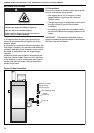
WARNING
Fire Hazard
Some objects will catch fire or explode when
placed close to heater.
Keep all flammable objects, liquids and
vapours the required distance away from the
heater.
Failure to follow these instructions can result
in death, injury or property damage.
1 m
Minimum
Roof
Wall
*If the point
of roof
intersection
is within 2.5 m
of a nearby
structure, the
flue must
terminate
at least
1 m above
that structure.
*Less than
2.5 m
Nearby
Structure
*1 m
Minimum
Flues up to 200 mm dia. are fitted
with Bird Screens, over 200 mm
with a Rain Cap.
Use adequate
support to
prevent heater
from carrying
the weight of
the flue.
135°
Roof
Wall
Minimum Total
1m +
(0.5m for each 135° bend) +
(1m for each 0.33m of flue
running in the 135° direction)
1 m
Minimum
above roof
Use adequate
support to
prevent heater
from carrying
the weight of
the flue.