


COMBAT
®
CABINET HEATERS INSTALLATION, COMMISSIONING, OPERATION AND SERVICE MANUAL
34
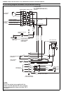
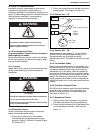
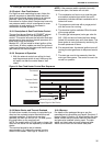
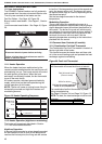
Figure 13: Combination Thermostat (all models)
10.2 Commissioning the Burner (gas heaters)
High/Low and modulating burners have additional
specific requirements. Follow the manufacturer’s
instructions using the data provided on Page 8,
Section 4.4 through Page 10, Section 4.7.
10.2.1 Gas Supply
All aspects of the gas installation, including the gas
meter, must be inspected, tested for soundness and
purged in accordance with local and national codes.
Ensure that the air is fully purged from the heater
inlet pipe up to the main gas valve inlet test nipple.
10.2.2 Before Operating the Heater
Ensure the burner head, air damper and pressure
switch settings are adjusted for the correct burner in
accordance with the Data Tables on Page 8, Section
4.4 through Page 10, Section 4.7 (see the burner
reference letter on data plate).
To ensure that all the controls are in safe working
order, operate the heater for the first time with the
isolating gas valve turned off.
1. Turn off the gas isolating valve
2. Using the installed external control, turn on the
burner. The automatic sequence will now begin
as described on Page 35, Figure 14.
There will be no ignition of the burner and lockout
will occur, which proves the controls are operating
correctly.
10.2.3 Fire the Burner for Dungs Combination
Gas Valves
1. Open the gas isolating valve.
2. Connect a suitable pressure gauge to the
burner pressure test point.
3. On models 040 or larger, to ensure that start
gas only may pass to the burner, remove the
gas valve electrical plug for the main gas valve.
4. Reset the lockout button of the control box and
the burner should now fire. If lockout should
occur when the start gas valve energises (or
the main gas valve for models up to 030),
repeat 3 or 4 times. If after several attempts the
burner does not fire, then turn the start gas
governor adjusting screw (or main gas gover-
nor for models 015 to 030) 3 turns clockwise.
See Page 34, Section 10.2.5 and repeat until
the burner fires.
10.2.4 Initial Setting
NOTE: Skip this step for models 015 to 030.
Once firing, the start gas pressure should be set to
the value given in the Data Tables for the burner
type and the model concerned (see the burner
reference letter on data plate). This is carried out by
turning the governor adjusting screw (accessed
under the black push-on cover) clockwise to
increase pressure, or counter clockwise to decrease
pressure.
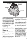
10.2.5 Set Gas Rate
1. Switch off and refit the main gas valve plug
(removed earlier to allow the main gas valve to
operate).
2. Switch on again and allow the burner to fire and
to settle for a few minutes.
3. Adjust the main gas burner pressure to the
value given in the relevant Data Table for the
model concerned using the Main Gas Regula-
tor (accessed under the swivel cover). See
Page 37, Figure 17.
The results of setting the gas flow rate by using
burner pressure only can lead to quite wide
variations in heat input due to the nature of the
burners used.
NOTE: If the correct burner pressure cannot be
reached, then check the inlet pressure to the valve,
with the burner firing. See Technical Data Tables on
Page 8, Section 4.5 for inlet pressure requirements.
Do not continue to adjust the regulator if the
pressure is not changing.
If the inlet pressure is too low to allow the correct
burner pressure setting, then the gas inlet pressure
must be corrected before completing the
commissioning.
10.2.6 Check Gas Rate
It is important to check that the gas rate set during
the commissioning is within ± 5% of the required
flow rate.
This may be achieved by checking the gas flow to
the heater wherever possible by using the gas meter
and timing the flow through the meter. The results
should be compared with the required flow rate for
the model given in the Data Tables, adjusting the
burner pressure to correct for any error.
Checking the gas rate must be carried out with all
other appliances including any pilots, turned off.
1. After burner pressure adjustment, allow the
heater to operate for at least 15 minutes and
then re-check settings.
2. Remove the manometer and refit all covers to
the valve and tighten the screw of the outlet
pressure tap.
C°
20
40
60
80
100
120
Set Point 1
Fan Off
Set to 38°C
Set Point 3
Limit
Set to 110°C
Set Point 2
Fan On
Set to 60-65°C