


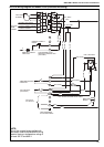

SECTION 9: WIRING AND ELECTRICAL INFORMATION
19
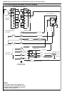
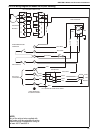
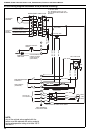
SECTION 9: WIRING AND ELECTRICAL INFORMATION
9.1 Electrical Supply
A 230 V 50 Hz 1 Ø supply is required for all heater
Models 015 to 030 connected to the heater terminals
L1, N and Earth.
Standard models 040 to 0100 and all High Flow
models require a 400 V 50 Hz 3 Ø and neutral
supply connected to the heater terminals L1, L2, L3,
N and Earth.
All heaters and controls must be correctly earthed.
All external wiring must comply with the relevant IEE
and local regulations and be carried out by a
qualified electrician.
It is important that "L and N" polarity is correct for
these heaters, as incorrect polarity may prevent the
burner control box from operating properly. It is also
important that the voltage between N and earth is at
0 V and can never exceed 15 V.
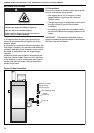
An isolator with a contact separation of at least 3
mm on all poles should be installed adjacent to the
heater, but not attached to it, to disconnect all
supplies to the heater and where necessary to
isolate the remote control panel.
The final connection to the heater should be made in
metal sleeved flexible cable or flexible conduit to the
main terminal block under the front lower panel of
the heater using 1 sq. mm cable. Model 0100 and
High Flow models with 5.5kW or 7.5kW motors use
1.5 sq. mm cable. Cable entry is provided into the
rear horizontal frame of the cabinet.
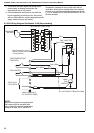
9.2 Remote Controls
The heater is designed to be operated by controls
installed remotely from the heater. See Page 20,
Section 9.3. through Page 27, Section 9.10.
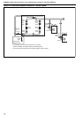
9.2.1 Burner Controls (Thermostat)
Controls to operate the burner must be voltage free
contacts connected between terminals 2 & 3 of the
main terminal block.
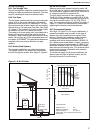
9.2.2 Positioning Room Thermostats or
Roberts-Gordon Control
A room thermostat or Roberts-Gordon control
should be mounted on a wall or column at a height
of approximately 1.5-1.8 metres from the floor to
measure the ambient temperature. It should be clear
of both cold draughts and the direct path of warm air
from the heater.
9.2.3 Remote Frost Thermostat
When required, connect to terminals 2 and 3 in the
main terminal block.
Locate the thermostat within the heated space
adjacent to the most vulnerable equipment that
requires protection.
See Page 20, Section 9.3 through Page 27, Section
9.10.
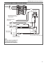
9.2.4 Controls for High/Low Burner Operation
For heaters with a high/low burner, the controls will
need to provide two stage signal to operate these
burners. This is best provided by a two stage
thermostat.
The thermostat may control the heater outlet
temperature if the heater is designed for a duct
distribution system or the room temperature.
The site wiring will be across terminals 2 and 3 for
any time control and the on/off function of the burner
(stage two), and across terminals 7 and 8 for the
high fire (first stage) setting.
The burner will then operate as follows:
Temp. from cold up to
the 1st set point ..................... Full fire at max. rate
Temp. above 1st set point
up to 2nd set point.................Low fire at min. rate
Temp. above 2nd set point ...............................Off.
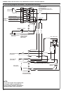
9.2.5 Controls for Fully Modulating Burners
For heaters that incorporate a fully modulating
burner, a special temperature control is provided
with the heater. On-site wiring of the temperature
sensor is required with any time control.
The heater will normally be controlled by the
temperature of the air in the outlet duct, but it is
possible to control on room temperature.
The position of the sensor in the outlet duct is
determined on site. Using a themometer, select a
position in the outlet duct approximately 1 m from
the heater, across the cross section of the duct that
provides a reasonable average of the temperatures
found. Mount the sensor at this position for best
results.
When operating at reduced heat input, the leaving
air temperature may be low when controlled on room
temperature.
The time control and any other on/off controls will be
across terminals 2 and 3. The sensor will be
connected to terminals 8 and 9.
The operation will occur in the following sequence:
1. The burner will fire. When the burner sequence
reaches the release to modulation stage, the
control will begin to monitor the outlet
temperature.
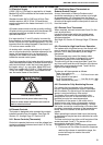
WARNING
Electrical Shock Hazard
Disconnect electrical power before servicing.
Failure to follow these instructions can result in
death or electrical shock.