


COMBAT
®
CABINET HEATERS INSTALLATION, COMMISSIONING, OPERATION AND SERVICE MANUAL
8
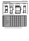
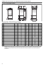
4.4 General Technical Data Table (all models)
Appliance Category II
2H/L 3B/P
NOTE: *Models 40 & 50 are available with 230 V 1 Ø electrical supply as an extra cost option.
A permanent uninterrupted electrical supply is required for all models.
When reading the following data tables, ensure that you are using the correct table for the burner and gas valve
installed. The data tables include a burner reference letter that can be found on the heater data plate. Refer to the
burner manufacturer’s instructions and the specific instructions supplement where applicable. The burner settings
shown in the instructions must be used for burner settings.
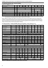
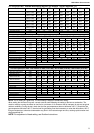
4.5 Technical Data - Ecoflam ON/OFF Burners (all models - burner reference "C")
NOTE: For adjustment of head setting, see Ecoflam Instructions
Model 015 020 030 040 050 060 070 080 0100
Electrical Supply* 230 V / 50 Hz / 1 Ø 400 V / 50 Hz / 3 Ø
Main Fan Motor Type Direct Drive Belt Drive
Motor Size (kW) 0.75 2.2 1.5 2.2 4.0
Motor Pulley (PCD) NA
2 A x
80 mm
2 A x 95 mm
2 A x
106 mm
Fan Pulley (PCD) NA
2 A x
180 mm
2 A x
180 mm
2 A x
180 mm
2 A x
180 mm
Start Current (Amps) 24 24 28 21 21 10.2 30 30 35
Run Current (Amps) 5.3 5.3 6.3 6.2 6.2 3.5 5.1 5.1 9.6
Airflow
(m
3
/h)
3398 3398 5097 6796 8495 11044 12443 12443 17330
Free Blowing
(ft
3
/min)
2000 2000 3000 4000 5000 6500 7500 7500 10200
Model 015 020 030 040 050 060 070 080 0100
Gross Heat Input
(kW)
(Btu/h) x (1000)
55.5
189.4
73.3
250.1
93.2
318.0
129.9
443.2
162.0
552.7
208.0
709.7
242.0
825.7
275.2
939.0
348.5
1189.1
Net Heat Input
(kW)
(Btu/h) x (1000)
50.0
170.6
66.0
225.2
84.0
286.6
117.0
399.2
146.0
498.2
187.4
639.4
218.0
743.8
248.0
846.2
314.0
1071.4
Heat Output
(kW)
(Btu/h) x (1000)
47.4
161.7
61.2
208.8
78.4
267.5
110.2
376.0
134.5
458.9
177.7
606.3
205.3
700.5
230.4
786.1
293.4
1001.1
Pressure Switch Setting (mbar) 1.5 4.5 4.0 6.5 5.0 6.5 7.5 7.0
Flue Static Pressure (mbar) -0.05 -0.05 -0.09 -0.30 -0.05 -0.25 -0.17 0.10 0.45
Gas Connection (in) 3/4" 1 1/4"
Natural Gas (G20) Data - Inlet Pressure 20 mbar (7.8 in WG) Min 17 mbar (6.8 in WG) Max 25 mbar (10 in WG)
Main Burner Gas Pressure mbar 4.0 2.7 4.2 4.8 7.7 5.2 7.1 9.5 10.0
Start Gas Pressure mbar NA NA NA 1.8 2.8 0.9 1.1 1.7 3.4
Gas Rate
(m
3
/h)
(ft
3
/h)
5.3
187
7.0
247
8.9
314
12.4
438
15.4
546
19.8
701
23.1
816
26.2
928
33.2
1175
Start Gas Orifice (mm dia) 5.0 6.0 7.0 7.0 7.0
Burner Type AZUR 60 BLU 120 BLU 120 BLU 170 BLU 250R BLU 250 BLU 250 BLU 250S BLU 350
Burner Head SSSSSSSSS
Burner Head Setting (mm) 0 10 11 15 14 24 24 24 21
Air Setting 2.6 4.2 6 2.2 3.5 2.9 3.6 1.4 1.6
Valve Type Main Gas
MBDLE
405
MBDLE
407
MBDLE
410
MBDLE
412
Valve Type Start Gas NA S.I.T. 0 832 051
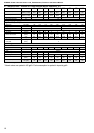
LPG Gas Propane (G31) Data - Inlet Pressure 37 mbar (14.6 in WG) Min 25 mbar (10 in WG) Max 45 mbar (18 in WG)
Main Burner Gas Pressure mbar 4.2 3.3 4.6 4.8 7.5 5.8 7.8 12.0 7.6
Start Gas Pressure mbar NA NA NA 1.6 2.5 0.8 1.0 1.5 3.1
Gas Rate
(m
3
/h)
(kg/h)
2.1
3.9
2.8
5.1
3.5
6.5
4.9
9.1
6.1
11.3
7.8
14.5
9.1
16.9
10.4
19.2
13.1
24.3
Start Gas Orifice (mm dia) 5.0 6.0 7.0 7.0 7.0
Main Gas Orifice (mm dia) 8.5 10.0 10.0 14.5 14.5 14.5 14.5 14.5
Burner Type
AZUR
60 AH
BLU
120 AH
BLU
120 AH
BLU
170 AH
BLU
250R AH
BLU
250 AH
BLU
250 AH
BLU
250S AH
BLU
350 AH
Burner Head S S S S S S S S LPG
Burner Head Setting (mm) 0 10 13 15 14 24 24 24 20
Air Setting 3.0 4.8 6.6 2.6 4.5 3.1 4.2 1.6 1.8
Valve Type Main Gas
MBDLE
405
MBDLE
407
MBDLE
410
MBDLE
412
Valve Type Start Gas NA S.I.T. 0 832 051