


SECTION 10: COMMISSIONING
35
3. Check gas flow rate at gas meter.
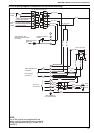
10.3 Control - Gas-Fired Heaters
For High/Low and modulating burners, follow the
general sequence as described below and also
have extra functional stages related to air damper
positions. Refer to the burner manufacturers
instructions for further detail. Gas burners have only
one pressure switch, which is configured to cover
combustion air and reaction to increases in
combustion chamber pressure.
10.3.1 Description of Gas-Fired Heater Control
The gas fired burner fitted to all COMBAT
®
cabinet
heaters is controlled by a full sequence plug-in
control. This control ensures the safe start and stop
sequence and also monitors the safe presence of a
flame and burner air pressure.
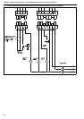
Models 015 - 030 are wired for direct ignition of the
main flame. All other models are wired for ignition of
a start gas flame as the first stage and then the main
gas flame as the second stage.
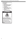
10.3.2 Sequence of Operation
1. With the external controls on calling for heat,
and the pressure switch at rest, the burner fan
will switch on after the control does a "self
check".
NOTE: If the pressure switch contacts (normally
closed) are open, the heater will not start.
2. The combustion air fan turns on and the pres-
sure switch contacts close within the next 5
seconds to indicate sufficient combustion air or
lockout will occur.
3. The sequence continues with a purge period
with the burner fan running.
4. The electrical ignition switches ON at the end
of the purge period.
5. The start gas valve opens (main gas valve for
015 - 030) and once a flame has been estab-
lished, this remains open until close down. The
flame probe is now continuously monitoring for
the safe presence of flame.
6. Five seconds later, the electric ignition turns off,
leaving the start gas flame to be proved as sta-
ble.
7. The start gas runs for ten seconds, then the
main gas valve opens. The control is now in its
normal run position
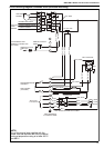
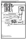
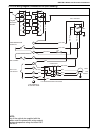
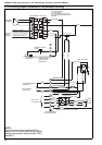
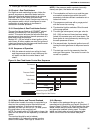
Figure 14: Gas-Fired Heater Control Box Sequence
10.3.3 Motor Starter and Thermal Overload
On belt-driven models, the motor is controlled by a
direct on-line contactor starter fitted with thermal
overload protection. If the thermal overload
operates, the main fan will not run. To reset, press
the reset button on the overload unit.
NOTE: For models with a 5.5 kW motor or larger, the
direct on-line starter will be replaced by a automatic
starter.
The overload should be set to indicate
approximately 0.2 A above the normal running
current of the heater. See Page 8, Section 4.4.
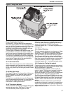
10.3.4 Burners
For details of the packaged burners, see the
manufacturer’s instructions and Page 8, Section 4.5
through Page 9, Section 4.6. When reading the data
tables, ensure that the correct table for the burner
and gas valve installed is being used. The data
tables are listed under a burner reference letter
which can be found on the heater data plate.
Thermostat
Motor
Pressure Switch
Transformer
Gas Valve
Ionization Probe
Necessary Input Signal
Output Signal of the Device
30 s 3 s
2 s
+
+