


COMBAT
®
CABINET HEATERS INSTALLATION, COMMISSIONING, OPERATION AND SERVICE MANUAL
40
SECTION 11: USER INSTRUCTIONS
11.1 User Instructions
The COMBAT
®
Cabinet heaters are fully automatic
and operate from the external controls fitted on site.
The only user controls at the heater are the:
Fan Run Button - See Page 40, Figure 20.
Burner lockout reset button - See Page 41, Section
11.2 .2.
Limit thermostat reset button - See Page 40, Figure
20.
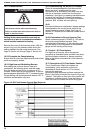
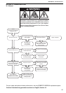
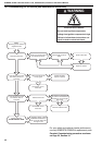
11.1.1 Heater Operation
When the heater has been switched on by the
remote controls installed on site, the main burner will
automatically turn on. The burner control will control
the safe ignition of the flame. When the heat
exchanger is sufficiently heated, the fan thermostat
turns on the main fan(s).
All heaters require a constant gas and electricity
supply, which must not be interrupted during the
normal operation of this heater.
NOTE: The fan will come on during burner firing for
horizontally mounted and high-flow heaters and
modulating burners.
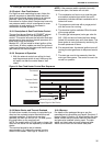
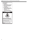
Figure 19: Heater Operating Sequence
11.1.2 Heater Operation (high/low or modulating)
The heater will operate as described in Section
11.1. 1 with these added features:
High/Low Operation
A second limit thermostat or a two-stage thermostat
will be installed on site so that as the temperature
reaches the first set point, the firing rate will reduce
to low fire. If the temperature rises to the second set
point, the burner will turn off. The burner will come
on again at either High or Low fire, depending on the
thermostat set point.
Set the two stage thermostat to the desired
temperature.
Modulating Operation
The on-site control for modulating burners is a
temperature controller that provides a varying output
signal dependant upon the ambient temperature to
the control. The burner firing rate will continuously
vary between the maximum and minimum setting. If
the temperature rises with the firing rate set to the
minimum, the burner will shut down. Set the
operating temperature according to the instructions
provided with the control.
11.2 Common User Controls (all models)
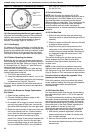
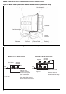
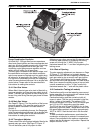
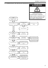
11.2.1 Combination Fan/Limit Thermostat
The Combination Fan/Limit Thermostat is located at
the top right side of the heater.
This control ensures the heater does not blow cold
air in the normal heating cycle and protects the heat
exchanger against overheating.
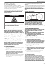
Figure 20: Fan/Limit Thermostat
WARNING
Electrical Shock Hazard
Disconnect electrical power before servicing.
Failure to follow these instructions can result in
death or electrical shock.
ON
RUN ON
CLOSE
DOWN
THERMOSTAT
CALL FOR
HEAT
BURNER
RUN
FAN
2-3 MINUTES
ON
ON
White fan button
Pull out for normal operation.
Press in for constant fan.
Red limit reset button
(Press to reset)
The combination fan/limit thermostat is preset
during commissioning.
See Page 8, Section 4.4 and Page 34, Figure 13.
NOTE: To reset, the heat exchanger must be cool.
If the air flow is reduced due to power failure, the
limit thermostat will cause the burner to lockout.
Description Part Number
Combination Fan/Limit Thermostat K017A