


COMBAT
®
CABINET HEATERS INSTALLATION, COMMISSIONING, OPERATION AND SERVICE MANUAL
48
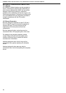
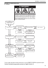
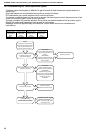
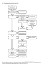
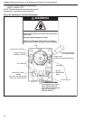
14.4 Troubleshooting for Flame Supervision System
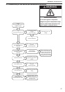
Heater Operating
TROUBLESHOOT ENDS.
If problems persist, contact
ROBERTS GORDON
®
at
Tel: +44 (0)121 506 7709
www.rg-inc.com
No
Control box faulty.
Replace with correct type.
Ye s
'Lockout' still occurs?
No
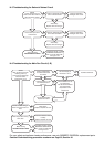
OIL-FIRED
Clean or replace photo
electric cell as necessary.
GAS-FIRED
Replace flame probe.
Check for it's correct position.
Check wiring to flame probe.
Check burner earth
connection.
Ye s
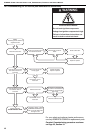
Does 'lockout' occur when
a flame is present?
Repair or replace.
OIL-FIRED
Is there a stray light entering
the burner or is there a
flame?
GAS-FIRED
Inspect and test the flame
probe and wiring for a short
circuit to earth.
Ye s
START
Connect a DC ammeter in
series with the flame monitor.
Turn on all controls and
ensure supply to burner
No
No
Is there a current flowing
in excess of the max.
value for NO flame?
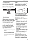
The flame supervision system is different for gas-fired and oil-fired heaters but may be tested in a
similar way.
Gas-fired heaters use a rectification flame probe to monitor the flame.
Oil-fired heaters use a photo sensitive cell to monitor the flame.
To connect a suitable meter into the circuit to monitor the flame signal current, disconnect one of the
wires to the monitor (there is only one for gas-fired).
Connect a suitable DC ammeter between the terminal just disconnected and the wire taken from it.
Should the meter read backwards, then reverse its connections.
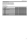
Readings should be approximately as follows(For further details see burner manufacturer’s
instructions):
Oil-Fired Gas-Fired
Maximum flame
current with no
flame
Minimum flame
current with
flame
Maximum flame
current with no
flame
Minimum flame
current with
flame
12 µ Amp 25 µ Amp 0.5 µ Amp 1.0 µ Amp