


SECTION 10: COMMISSIONING
37
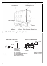
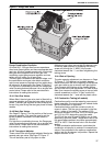
Figure 17: Dungs Gas Valve
10.4 Gas Valves
Dungs Combination Gas Valve
All model 015 - 030 gas-fired burners operate as
direct main flame ignition and have no separate start
gas train. All other models operate with a first stage
start gas flame supplied from a start gas train
containing a start gas pressure regulator and two
safety shut-off valves, for all gas types.
The main gas is released at the second stage, and
the combination main gas valve block contains a
main burner pressure regulator and two safety shut-
off valves, for all gas types. See Page 37, Figure 17.
For high/low or modulating burners, the Dungs gas
valve has extra features because it is an air/gas ratio
control valve. Please refer to the manufacturer’s
instructions for setting the controls.
10.4.1 Start Gas Valves
Where fitted, the start gas valve train is fitted with a
pressure regulator and two start gas safety shut off
valves. The start gas regulator is used to adjust the
burner firing rate during the start gas phase of these
models.
10.4.2 Main Gas Valves
See Page 37, Figure 17 for the position of the burner
pressure regulator. This must be used to set the
burner pressure indicated in the data tables in
Section 4.
For high/low or modulating burners, the Dungs gas
valve has extra features because it is an air/gas ratio
control valve. Please refer to the manufacturer’s
instructions for setting the controls.
10.4.3 Throughput Adjuster
These valves have a throughput adjuster fitted to the
second main gas valve. See Page 37, Figure 17.
This will be factory set at fully open on new
appliances and need no further adjustment. When
replacing a gas valve, ensure that this device is set
in the fully open position by releasing the locking
screw and turning the "V MAX" fully counter-
clockwise towards the "+" and then retightening the
locking screw.
10.4.4 Rate of Opening
The slow opening adjustment can be seen on Page
37, Figure 17. This device is a hydraulic damper
which slows down the rate of opening of the second
main gas valve to give a smooth main gas ignition.
This is preset at the factory at the slowest setting
and will need no further adjustment. If a new valve is
fitted, then remove the plastic screw on top and with
a small screwdriver turn the "V Start" screw fully
clockwise towards the "-" and refit the plastic cover.
10.5 Combustion Testing (all models)
Combustion quality must be tested to prove correct
heater operation. Incorrect results will indicate faults
with the installation or appliance.
Combustion testing must be carried out with all
covers in place. The flue gas is sampled in the flue,
within 1 meter of the heater. The values of CO
2
should be between 9.5% and 10.0% for natural gas
and 11% for LPG, depending upon the model.
The CO will be up to 80 ppm (0.008%) dry, air free,
depending upon the model. Temperature rise of the
flue gases above ambient should be approximately
160°C to 180°C. Seal the test hole in the flue after
testing.
To alter combustion performance, open/close the
combustion air damper to reduce or increase these
values. Once adjusted to the optimum combustion
setting, lock the air damper into position. Repeat the
steps in Section 10.2.6.