


SECTION 8: FUEL PIPING
17
8.2 Fuel Oil Supply
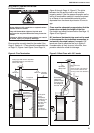
8.2.1 Fuel Storage Tank
The fuel storage tank should be located outside the
building as close as possible to the heater. The tank
must be installed per local and national codes.
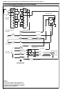
8.2.2 Fuel Pipes
The fuel pipes must be sized to ensure an adequate
supply of oil to the entire installation. Galvanised
pipe must not be used for oil installations. The fuel
pipe must terminate at each heater with an isolating
manual valve, a fire valve and a fuel filter. See Page
12, Figure 3. The fusible link of the fire valve should
be installed 100 mm (4 in) above the burner.
The heater’s oil burner pump inlet is provided with a
flexible oil line which should be used for the final
connection. When making the final connection to the
heater, do not block any of the removable panels of
the heater. All COMBAT
®
oil-fired cabinet heaters are
supplied with burner pumps fitted for one pipe
systems.
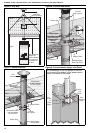
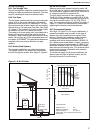
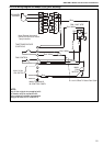
8.2.3 Gravity Feed Systems
The simplest installation is a gravity feed system.
This system relies on the head of the fuel to push
the fuel through the system. See Page 12, Figure 3.
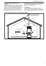
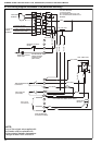
8.2.4 B. M. Oil Lifter
Where a gravity feed system cannot be used, a B.
M. oil lifter may be used for small installations up to
the equivalent of a single model 050 on minimum lift
or a single model 020 on maximum lift.
The fuel output from the oil lifter is gravity fed.
The B. M. oil lifter requires a constant 230 V 50 Hz
1 Ø electrical supply. The maximum pipe size to be
used on the suction side is 1/4" ID, 5/16" OD (8
mm). For maximum loading of oil lifters See Page 17,
Figure 11. Consult the manufacturer’s information
regarding the need to prime these devices.
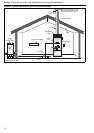
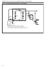
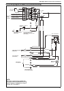
8.2.5 Pressurised Systems
See Page 18, Figure 12. For larger installations, a
pressurised system may be used. In this type of
system the pump draws fuel from the tank, then
pushes it through the installation under pressure.
The pressure is controlled at the pump by a
pressure relief valve at approximately 0.8 BAR (12
psi). When a presurised system is used, a pressure
reducing valve set at approximately 0.3 BAR (5 psi)
should be installed on the fuel inlet to each heater
after the manual isolating valve. This protects the oil
pump from the danger of possible over pressure
under fault conditions.
The electrical supply for the pump installation will
depend upon the type of pumps chosen, but will
normally be set to run continuously.
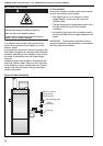
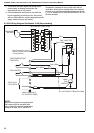
Figure 11: B. M. Oil Lifter
Technical Data
Maximum Lift............. 8 m
Maximum Capacity.... 20 L/h
Actual Capacity.......... 10 - 20 L/h
Dependant upon vertical lift and suction
line length.
Max 3m
Min 0.15m
Max 8m
Min 0.15m
Flow Output - L/h
Flow Output - UK gal/h
240 V
Oil Lifter
Air Vent
Filler Pipe
Storage Tank
50 mm
Total Suction Length in Feet
8mm (5/16”) O.D. Copper Tube
Lift in Feet
Lift in Metres
0 5 10 15 20 25
0 1 2 3 4 5 6 7 8
25
20
15
10
5
0
6
5
4
3
2
1
0
33’
65’
99’
132’
165’
Oil
Heater