


COMBAT
®
CABINET HEATERS INSTALLATION, COMMISSIONING, OPERATION AND SERVICE MANUAL
38
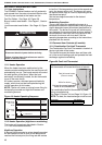
10.5.1 Pressure Switch
Setting of the pressure switch must only be
carried out as part of a complete commission
which includes combustion testing.
Remove the cover of the pressure switch. With the
burner firing, turn the pressure switch dial to the
setting indicated for that model and burner. See
Page 8, Section 4.5 through Page 9, Section 4.6.
10.5.2 Complete the Commissioning
Ensure that all covers are fitted correctly and all test
points are properly sealed.
10.5.3 High/Low and Modulating Burners
After setting the minimum burner input and
combustion, the following check must be made:
Run the heater on low fire for a minimum of 15
minutes. Check the flue gas temperature. If the flue
gas temperature falls below 125° C, increase the low
fire gas setting until the temperature reaches 125° C,
otherwise condensation may form.
10.6 Commissioning the Burner (Oil Heaters)
Check all valves between the fuel tank and the
heater are open, including the fire valve.
Ensure that oil is available at the heater inlet and
that the air has been vented from the fuel pipe
installation. Vent the air by opening the bleed screw
on top of the fuel filter. On pressurised systems,
check that the installation is running at the correct
pressure. B.M. oil lifters will need priming.
10.6.1
Ensure that the burner head and air damper settings
are adjusted for the correct burner and that the
correct atomising nozzle is fitted. See Page 10,
Section 4.7 and the burner reference number on the
data plate.
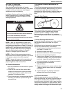
10.6.2 Preparation for Burner Pressure Test
Attach a pressure gauge 0-15 BAR (0 - 200 psi) to
the burner pump pressure test port. (See
manufacturer’s information). A test manifold gives
you the facility for the connection of the pressure
gauge and the venting of the pump.
10.7 Control - Oil-Fired Heaters
For High/Low oil burners, follow the general
sequence as described below and also have extra
functional stages related to air damper positions.
Refer to the burner manufacturer’s instructions for
further detail.
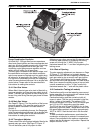
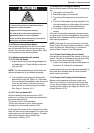
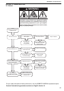
10.7.1 Description of Oil Fired Heater Control
The oil fired burners fitted to the heater are
controlled by a fully automatic control and
photoelectric flame monitor unit. This control
ensures the safe start,
ignition and stop sequence and also monitors the
flame. If the flame should fail the control will go into
"lockout". The button on ther front of the control will
illuminate to indicate lockout. Press the button to
reset the control to restart the burner firing cycle.
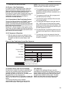
Figure 18: Oil-Fired Heaters Control Box Sequence
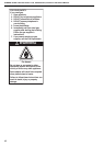
WARNING
Electrical Shock Hazard
Use extreme caution while commissioning.
Failure to follow these instructions can result in
death or electrical shock.