


SECTION 4: SPECIFICATIONS
9
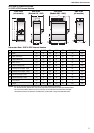
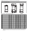
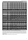
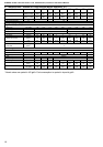
4.6 Technical Data - Ecoflam Modulating Burners (all models - burner reference "H")
NOTE: The air setting is a guide only. The final setting is subject to combustion testing.
When setting the minimum firing rate, a check must be made following the setting of the burner combustion. The
check is made by running the heater on low fire for a minimum of 15 minutes at the full transport air rate and at typical
ambient conditions. During the test, check that the flue gas temperature does not fall below 125° C. Should the flue
gas temperature fall below 100° C, then the low fire gas setting must be increased to a value that will achieve 125° C
flue gas temperature; otherwise condensation may form in the heat exchanger and flue, causing rapid corrosion and
short operational life.
NOTE: For adjustment of head setting, see Ecoflam Instructions.
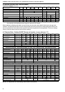
Model 015 020 030 040 050 060 070 080 0100
Maximum Gross Heat Input
(kW)
(Btu/h) x (1000)
55.5
189.4
73.3
250.1
93.2
318.0
129.9
443.2
162.0
552.7
208.0
709.7
242.0
825.7
275.2
939.0
348.5
1189.1
Maximum Net Heat Input
(kW)
(Btu/h) x (1000)
50.0
170.6
66.0
225.2
84.0
286.6
117.0
399.2
146.0
498.2
187.4
639.4
218.0
743.8
248.0
846.2
314.0
1071.4
Minimum Gross Heat Input
(kW)
(Btu/h) x (1000)
38.9
132.7
51.3
175.0
65.2
222.5
90.9
310.2
113.4
386.9
145.6
496.8
169.4
578.0
192.6
657.2
244.0
832.5
Minimum Net Heat Input
(kW)
(Btu/h) x (1000)
35.0
119.4
46.2
157.6
58.8
200.6
81.9
279.5
102.2
348.7
131.2
447.7
152.6
520.7
173.6
592.3
219.8
750.0
Maximum Heat Output
(kW)
(Btu/h) x (1000)
47.4
161.7
61.2
208.8
78.4
267.5
110.2
376.0
134.5
458.9
177.7
606.3
205.3
700.5
230.4
694.0
293.4
1001.1
Minimum Heat Output
(kW)
(Btu/h) x (1000)
33
113
43
147
55
188
77
263
94
321
124
423
144
491
161
549
205
699
Pressure Switch Setting (mbar) 1.5 1.0 1.5 2.0 2.5
Flue Static Pressure (mbar) -0.05 -0.05 -0.09 -0.30 -0.05 -0.25 -0.17 0.10 0.45
Gas Connection (in) 3/4" 1 1/4"
Natural Gas (G20) Data - Inlet Pressure 20 mbar (7.8 in WG) Min 17 mbar (6.8 in WG) Max 25 mbar (10 in WG)
Main Burner Gas Pressure (mbar) 4.9 2.4 3.3 4.1 6.7 5.2 6.7 8.0 8.6
Min. Burner Gas Pressure (mbar) 3.2 2.8 2.4 2.3 3.7 2.5 3.4 4.3 5.4
Start Gas Pressure (mbar) NA NA NA 1.1 1.8 0.6 0.7 0.9 1.0
Maximum Gas Rate
(m
3
/h)
(ft
3
/h)
5.3
187
7.0
247
8.9
314
12.4
438
15.4
544
19.8
699
23.1
816
26.2
925
33.2
1172
Minimum Gas Rate
(m
3
/h)
(ft
3
/h)
3.8
134
5.0
177
6.3
222
8.8
311
11.0
388
14.2
501
16.5
583
18.7
660
23.7
837
Start Gas Orifice (mm dia) NA NA NA 7.0
Burner Type AZUR 60 BLU 120 BLU 120 BLU 170 BLU 250R BLU 250 BLU 250 BLU 250 BLU 350
Burner Head S S S S S S S S S
Burner Head Setting (mm) 0.0 8.0 10.0 15.0 14 T.O.
Low Flame Air Orange Cam ** 20° 13° 22° 18° 22° 25°
High Flame Air Red Cam ** 33° 40° 80° 30° 32° 30° 35° 55° 60°
Gas Valve Setting 0-1, 5 0-1 0-1, 4
Valve Type Main Gas MBDLE 407 MBDLE 412
Valve Type Start Gas NA S.I.T. 0 832 051
LPG Gas Propane (G31) Data - Inlet Pressure 37 mbar (14.6 in WG) Min 25 mbar (10 in WG) Max 45 mbar (18 in WG)
Main Burner Gas Pressure (mbar) 4.3 5.7 4.7 3.1 5.9 5.3 7.2 9.0 6.4
Min. Burner Gas Pressure (mbar) 2.3 2.9 1.4 1.6 2.0 2.3 2.5 3.2 2.0
Start Gas Pressure (mbar) NA NA NA 1.1 1.7 0.6 0.7 0.7 1.5
Maximum Gas Rate
(m
3
/h)
(kg/h)
2.09
3.87
2.76
5.11
3.51
6.49
4.89
9.05
6.10
11.29
7.83
14.49
9.11
16.86
10.36
19.18
13.12
24.29
Minimum Gas Rate
(m
3
/h)
(kg/h)
1.46
2.71
1.93
3.58
2.46
4.55
3.42
6.34
4.27
7.90
5.48
10.15
6.38
11.80
7.25
13.42
9.18
17.00
Start Gas Orifice (mm dia) NA NA NA 7.0
Main Gas Orifice (mm dia) 8.5 10.0 14.5 NA
Burner Type AZUR 60 BLU 120 BLU 120 BLU 170 BLU 250R BLU 250 BLU 250 BLU 250 BLU 350
Burner Head S S S S S S S S S
Burner Head Setting (mm) 0.0 8.0 10.0 15.0 14 T.O.
Low Flame Air Orange Cam ** 20° 13° 22° 18° 22° 25°
High Flame Air Red Cam ** 33° 40° 80° 30° 32° 30° 35° 55° 60°
Gas Valve Setting 0-1, 4 0, 3-0, 9 0-1, 1 0-1, 4 0-1, 5 0-0, 85
Valve Type Main Gas MBDLE 407 MBDLE 412
Valve Type Start Gas NA S.I.T. 0 832 051