


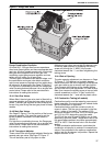

SECTION 10: COMMISSIONING
33
SECTION 10: COMMISSIONING
Installation, service, commissioning and annual
inspection of the heater must be done by a
contractor qualified in the installation and service of
gas or oil-fired heating equipment. Read this manual
carefully before installation, commissioning,
operation or service of this equipment.
10.1 Pre-Commission Checks
All pre-commission checks must be carried out
before lighting the heater.
Ensure that the heater and all controls are suitable
for the fuel, pressure and electrical supply to which
they are to be connected.
10.1.1 Louvers
Where fitted, the air delivery louvers need to be set
during commissioning to give the required air
distribution.
10.1.2 Electrical Checks
All pre-commission checks must be carried out
before commissioning the heater.
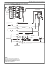
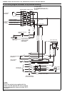
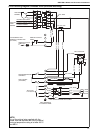
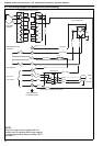
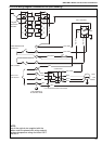
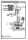
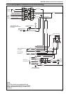
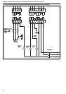
1. Check that all site wiring is connected in
accordance with the appropriate wiring dia-
grams on Page 20, Section 9.3 through Page
32, Section 9.15.
2. Check the correct fuse size is fitted in the local
supply isolator. See Page 8, Section 4.4.
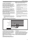
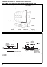
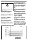
10.1.3 Polarity Test - 1 Ø
10.1.4 Polarity Test - 3 Ø
Voltage between each phase L1, L2 and L3 and
Earth or Neutral should be approximately 230 V.
Voltage between any 2 phases should be
approximately 400 V. Test Neutral to Earth as single
phase.
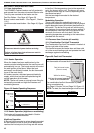
10.1.5 Fan Rotation Check
Switch on the electricity supply at the isolator and
the manual switch to "fan on" (if no remote fan switch
is installed, press the white button on the fan/limit
thermostat). On 3 Ø heaters, check the rotation of
the main fan. Rotation should be clockwise looking
at the drive end. If rotation is not correct, turn off the
isolator and change over any two of the incoming
supply phases and recheck. It will be necessary to
remove the lower front or right side panel to see fan
rotation.
10.1.6 Fan Motor Overload Check
On 3 Ø belt drive heaters, check the correct settings
of the fan motor overload. This should be 0.2 A
above the rated current on the heater data plate.
See Page 8, Section 4.4.
10.1.7 Mechanical Checks
1. Check that the flue is installed in accordance
with these instructions and local regulations.
2. Check that the settings of the Combination Fan/
Limit thermostat are correct - See Page 34,
Figure 13.
WARNING
Electrical Shock Hazard
Use extreme caution while commissioning.
Failure to follow these instructions can result in
death or electrical shock.
WARNING
Cut Hazard
Turn off fuel and electrical supply before maintenance.
Fan can start automatically at any time.
Failure to follow these instructions can result in severe
injury or product damage.
L
N
Less Than
0.1 ohm
ohm
V
230v 50Hz AC
V
0v
(must be less than 15v)
Supply
Earth
Terminal