


435/485/535
3-47
F3-69
(SET)
OFF
CRUISE
N
1
3
2
4
N
N
R
ON
STOP
F3-66
F3-63
N
R
ON
STOP
AUTO
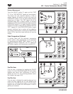
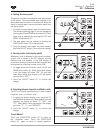
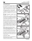
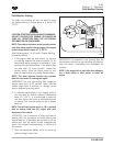
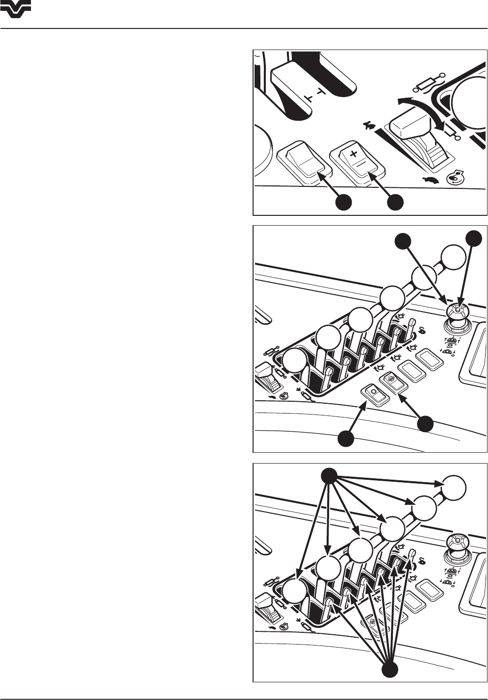
Cruise Control Operation
Cruise control automatically keeps the engine speed
at a specified RPM. Two switches control cruise
mode operation. The “CRUISE/OFF” switch (1)
enters and exits cruise mode. The “+/- (SET)” switch
(2) adjusts the cruise setting. When cruise mode is
activated, the engine returns to the last cruise
setting, if possible, based on throttle lever position.
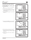
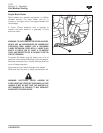
PTO Engagement Switch - yellow (optional)
To engage the PTO depress the button (3) in the
center of the PTO engagement switch (4) and pull the
knob upwards. To disengage the PTO, push the knob
down.
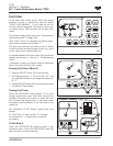
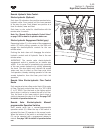
CAT TA22 Transmission Autoshift Switch
(optional)
Press and release the front/symbol of autoshift
momentary switch (5) to engage the transmission auto
shift. The letter “A” will be displayed in the powershift
display when autoshift is engaged. Press and release
the switch again to disengage the autoshift function.
See page 3-64 for details of operation.
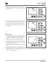
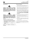
Differential Lock Switch (optional front & rear)
Press the front/symbol of differential lock switch
(6) to engage the self-holding differential. The DIFF
LOCK warning light will illuminate on the EIC when
the differential lock is engaged. Press the rear of the
switch to disengage. See page 3-66 for details of
operation. The differential lock will disengage if the
back part of the switch is depressed, if the foot brake
is applied or when ground speeds exceed 16 KPH (10
MPH).
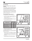
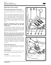
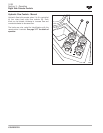
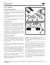
Remote Hydraulic Valve Controls - Manual
Note: See “Remote Control Valve Operation” on page
3-74 for details of operation before use.
Up to six remote hydraulic control levers (7) are
located on the right console. These are color-coded to
match the quick couplers at the rear of the tractor.
The levers have four positions: neutral, extend (or
raise), retract (or lower) and float, as indicated by the
decals. When not in use, the levers should be in the
neutral position where they can be locked to prevent
accidental actuation.
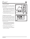
Lockout Levers - Manual
Below each control lever is a corresponding lockout
lever (8) to prevent or limit travel of the control lever.
See page 3-75 for details of operation.
1 2
4
3
5
7
8
Section 3 - Operation
Right Side Console Controls
6