


435/485/535
3-81
F3-98
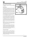
Hydraulic Motor Applications
The hydraulic system is a load sensing, pressure and
flow compensating system. Pressure and flow are
regulated by a load sensing line from the implement
valve. For proper and efficient use of the system, low
volume open center hydraulic motors or closed center
system motors with restricting orifices removed and
bypass valve closed should be used. Motor speed
must be regulated with tractor implement valve flow
control rather than bypass valves and orifices at the
motor. This will reduce heat buildup, save oil for other
simultaneous operations of the implement valve, and
increase system reliability.
1. Use hydraulic motors designed for closed center or
pressure/flow load compensating hydraulic systems
only. Do not use a hydraulic motor designed for
open center hydraulic systems unless it is adapted
for use by removing the inlet restrictor.
2. Be sure the hydraulic motor does not have restrictors
in the ports or fittings.
3. Hydraulic motors rated at less than 37.85 L/min
(10 US GPM) may be equipped with 12mm (1/2
")
ID hoses and standard (ASAE/SAE/ISO) couplers.
4. Hydraulic motors rated at greater than 10 US
GPM (37.85 L/min) should be connected with
19 mm (3/4
") hoses and (ASAE/SAE/ISO) couplers
to prevent excessive restriction and heat
generation.
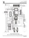
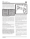
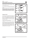
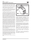
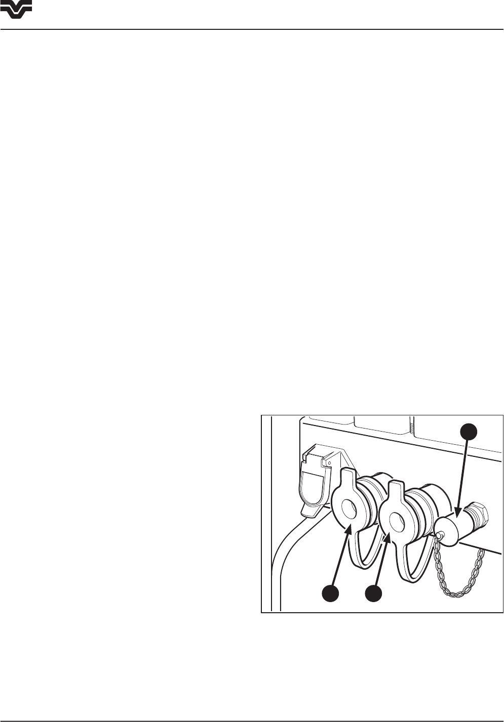
Low Pressure Return Circuit - Case Drain
A case drain line (1) is available to connect the return
line from the hydraulic motor or implement to the
coupler. This low pressure return circuit will reduce
back pressure in the remote hydraulic return line which
will result in more efficient hydraulic motor operation.
The return circuit can also be used in applications
where low return oil pressure is desired to improve
implement operation such as orbit motor case drain
lines.
NOTE: Connectors and couplers are available from
your Buhler Versatile authorized dealer.
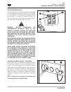
Optional Hydraulic Equipment - 19 mm (3/4")
Coupler Kit
An optional coupler Kit: (BVI P/N: 86033182) is
available for hydraulic motors that require 19 mm
(3/4") couplers. The kit includes supply (2) and return
(3) couplers that are fitted below the main valve
coupler assembly.
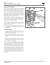
Operating remote equipment simultaneously
or remote equipment and hydraulic lift
simultaneously
NOTE: Hydraulic pump output varies with engine
speed. Oil flow will be relatively constant in the remote
control valve circuits if the flow control valve is used
to provide reduced oil flow, thus providing constant
operating speed for hydraulic motors, etc. even if
engine speed varies. Maintain the engine speed above
the minimum required for simultaneous operation of
all required circuits and vary ground speed by selection
of the appropriate gear ratio.
If operating two or more remote control valves
simultaneously or remote valves and 3-point hitch,
the flow control should be adjusted to provide a partial
flow to each valve circuit. (The hydraulic system of the
tractor is designed to provide adequate oil flow to the
implement valve to satisfy system demand, regardless
of the number of valve sections that are activated
(i.e. running an air seeder fan motor and lifting the
cultivator).
By adjusting the flow control of each valve section,
the system performance will be maximized and will
show up as proper performance of the implement
functions.
1
3 2
Section 3 - Operation
Hydraulic Operation - Manual