


3-88
435/485/535
Section 3 - Operation
Hydraulic Operation - Electro-hydraulic
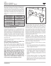
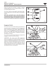
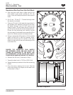
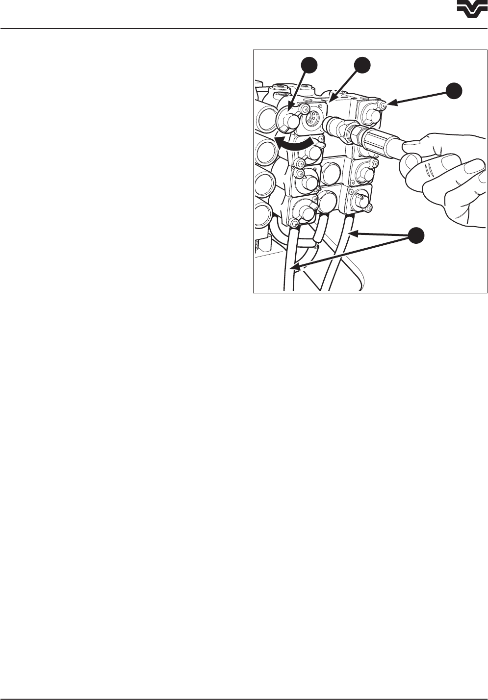
Hydraulic Quick Couplers
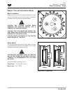
Each remote valve section has a pair of hydraulic
quick couplers located at the rear of the tractor. These
are color-coded with the hydraulic control levers in
the cab. The couplers are self-sealing and leverless
and require no tools for connecting and disconnecting
hoses. The couplers also permit hoses to detach
themselves from the coupler should an implement
become disconnected from the tractor.
The left section couplers (2) are identified by an
“extend/raise” symbol on the couplers dust cover and
the right section (3) are identified by a “retract/lower”
symbol on the couplers dust cover.
Excess oil drain hoses (4) are attached to each coupler
to drain away oil released during connection and
separation of the couplers.
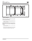
The couplers will accept standard (1/2
") SAE or ISO
tips. The couplers can be connected or disconnected
under pressure.
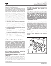
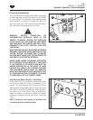
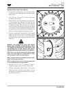
Coupler Connection
1. To connect couplers, wipe the outside of the coupler
and the tip of the implement to remove any dust
and minimize contamination.
2. Swing the dust cover (5) aside and insert the hose
into the coupler, making sure the hose is properly
seated.
3. Actuate the remote valve to supply hydraulic
pressure which will complete the hydraulic coupling
of the tractor and implement.
To ease removal and installation of the couplers,
relieve the pressure in the system. Securely support
the implement. Make sure no one will be injured by
moving equipment when relieving pressure in the
system. Move the control switch to the float position
with the engine running. This will relieve the pressure.
Turn the engine off with the control switch still in
float. After the engine is shut down return the control
switch to the neutral position. The couplers can now
be connected or disconnected with minimal pressure
and effort.
F3-96
3
25
4