


3-80
435/485/535
Section 3 - Operation
Hydraulic Operation - Manual
Operating Continuous Flow Hydraulic Equipment
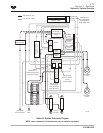
Continuous flow hydraulic equipment (i.e., hydraulic
motors) should be connected as per the table below
depending on the coupler manifold configuration. The
supply hose is connected to the a left coupler and the
return hose is connected to the corresponding right
coupler.
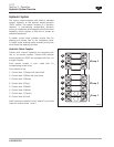
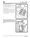
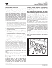
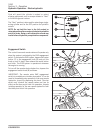
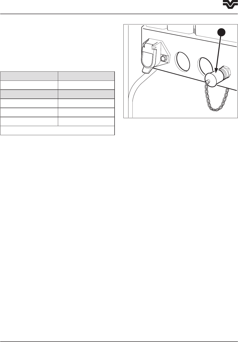
Low Pressure Return Circuit
A low pressure return line (1) is installed below the
hydraulic couplers that runs directly back to the
hydraulic reservoir. The low pressure return circuit will
reduce back pressure in the remote hydraulic return
line which will result in more efficient hydraulic motor
operation. The return circuit can also be used in
applications where low return oil pressure is desired
to improve implement operation such as orbit motor
case drain lines.
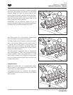
Connect the return line from the hydraulic motor or
implement to the coupler.
NOTE: Connectors and couplers are available from
your Buhler Versatile authorized dealer.
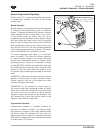
Use the flow control knobs to regulate the motor
speed. This will ensure that the hydraulic system will
supply only the oil required by the motor. This will
allow higher oil flow reserve for other valve sections
and their oil circuits.
NOTE: Hydraulic motors that are equipped with (1/2")
supply and return hoses, and require less than 10
GPM, can be hooked up directly to the gray couplers.
Hydraulic motors that have (3/4") supply and return
hoses, and require greater than 37.85 L/min (10
GPM), should be hooked up to the optional (3/4")
coupler kit. See “Optional Hydraulic Equipment” later
in this section for more information on this kit.
F3-97
1
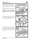
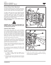
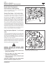
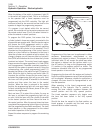
With the remote control valve lever fully forward in
the float position, the motor will be stationary. The
hydraulic motor will operate if the lever is moved to
the retract position. To stop the motor, move the lever
from the retract position to the float position. In the
float position, the motor will be able to stop slowly,
which will not damage the motor. When moving from
the float position to the neutral position, i.e., for road
travelling, move through the retract position quickly to
prevent pressurizing the circuit.
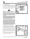
IMPORTANT: When operating continuous flow
equipment, the remote control valve lever must not be
moved from the full on position to the neutral or raise
positions as damage to the equipment may result. Use
the lockout levers on the control levers to prevent the
levers from moving to these positions.
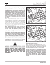
Observe the following to further protect the tractor
and equipment:
• Do not open any bypass valve in the equipment or
motor. Use the flow control valve to control the rate
of flow or speed of the motor.
• Do not hold the remote control valve lever to operate
the equipment. If the detent will not hold the lever
in the retract position, check the equipment for
proper adjustment or contact your dealer for
assistance in adapting the equipment to suit the
tractor.
• To ensure optimum hydraulic oil cooling, operate
continuous flow equipment at the highest flow
setting (by use of the flow control valve) and lowest
engine speed that will give the required machine
performance and speed.
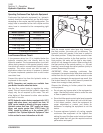
Manual hydraulics Connect to row
4 to 6 Section 3 to 6
Electro-hydraulic Connect to row
4 section 4
6 set (high flow) 4 or 6
8 set (high flow) 5 or 8
(1 starting at the bottom)