


435/485/535
3-25
Section 3 - Operation
Electronic Instrument Cluster - EIC
F3-29
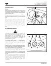
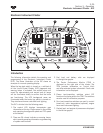
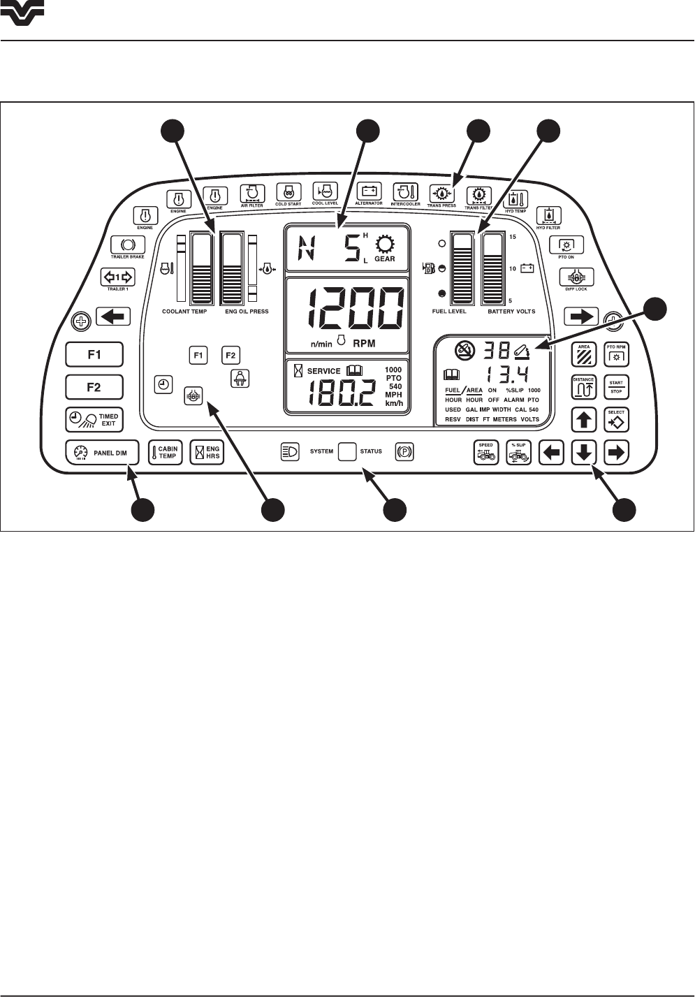
Electronic Instrument Cluster
1
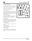
Introduction
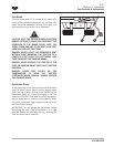
The following information details the operation and
programming of the Electronic Instrument Cluster
(EIC).
The above illustration of the EIC shows an
example of a normal operating display.
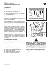
When the key-start switch is turned on, a self-test of
all the Liquid Crystal Display (LCD) segments and
warning lamps is activated, the audible alarm will
sound for approximately one second and all lamps
will be illuminated briefly to confirm that the bulbs
are functioning. The LCD background areas are
illuminated when the tractor key switch is turned on.
They also have dimmer controlled back lighting.
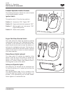
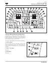
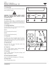
The EIC is divided into the following areas:
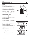
1. The central LCD displays transmission gear
information at the top. Engine speed in the middle
and operating hours/ground speed and PTO speed
at the bottom.
2. There are 26 colored indicator or warning lamps,
which provide operating information or give warning
of system malfunctions.
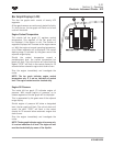
3. Fuel level and battery volts are displayed
in the right bar graphs.
4. The Tractor Performance Monitor (TPM) is
displayed on the right side of the cluster. The
TPM provides information on 3-point hitch
and other selected system information. Fault code
information is also displayed.
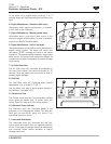
5. Eleven touch-sensitive switches select EIC
functions for display within the TPM. The switches
are also used for calibration purposes.
6. Four touch-sensitive switches are used to control
timed exit, cabin temperature (optional), engine
hours and instrument lighting.
7. Coolant level and engine oil pressure are displayed
in the left bar graphs.
2 3
4
526
7
2