


Installation
2-13
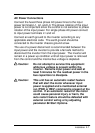
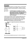
Relay Outputs
Programmable relay outputs are available for external monitoring
of the drive condition. These outputs are available at terminals
NO (Normally Open) and NC (Normally Closed) with a common
at terminal RCM (Relay Common). The circuit must be
completed by connection at terminals NO or NC and returned to
RCM. The output condition for terminals NO and NC is
programmed in parameter 75- Relay Output Select. The relay
outputs are rated at 115 VAC and 1 Amp maximum.
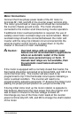
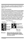
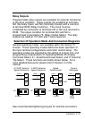
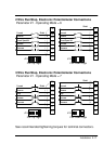
Selection Of Operation Mode And Connection Diagrams
Several operating modes are available within the Series 10
inverter. These operating modes define the basic operation of
the input terminal configurations and motor control setup. The
operating modes are selected by the setting of jumper J19, and
programming of parameters 21-Operating Mode, 24-Analog
Command Select, 41- Accel/Decel/Coast Select, and 77-External
Trip Select. These functions are briefly shown below. For a
more detailed discussion please refer to Section 3 of this
manual.
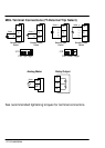
J19 J19 J19 J19
0Ć10VDC
0Ć5VDC 0Ć5VDC 0Ć20 or
4Ć20mA
CM
REF
VIN
Shield
-
+
CM
REF
VIN
Shield
-
+
CM
REF
VIN
Shield
-
+
CM
REF
VIN
Shield
CW
5.2VDC
0-10VDC
External
Speed Reference
0-5VDC External
Speed Reference
Speed
Potentiometer
Current
Reference
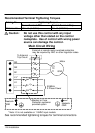
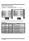
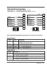
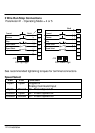
See recommended tightening torques for terminal connectors.