


Installation
2-5
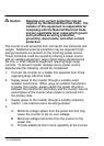
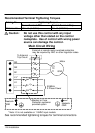
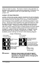
Caution: Do not use power factor correction
capacitors on the input power lines to the
inverter or damage to the control may result.
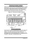
All external control wiring to the inverter should be run in a
separate conduit from all other wiring. The use of shielded
twisted pair wire is recommended for all control wiring. The
shield of the control wiring should be connected to control
terminal CM of the inverter only. The other end of the shield
should be taped to the wire jacket to prevent electrical shorts.
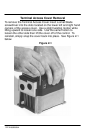
Conduit openings are provided at the bottom of the inverter
housing to allow power and control wiring entrance to the control.
Please refer to the inverter outline drawings located in Section 5
of this manual for sizes of the conduit openings.
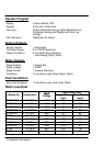
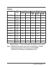
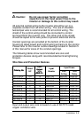
The following tables show recommended wire size and
protection devices along with recommended terminal tightening
torques.
Wire Size and Protection Devices
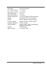
Catalog No
Rated
Input/
Out
p
ut
In
p
ut
Input Fuses
Catalog No.
Rated
HP
O
u
tp
u
t
Wire
AWG C
Inp
u
t
Breaker
Fast Time
HP
Wire
AWG Cu
Breaker
Acting Delay
ID101F50-E 0.5 14 240V/10A 240V/5A 240V/3A
ID10101-E 1 14 240V/15A 240V/10A 240V/6A
ID102F50-E 0.5 14 240V/10A 240V/5A 240V/3A
ID10201-E 1 14 240V/15A 240V/10A 240V/6A
ID10202-E 2 14 240V/20A 240V/20A 240V/12A
ID10203-E 3 14 240V/25 240V/25 240V/15
ID10205-E 5 12 240V/40 240V/35 240V/25
ID10401-E 1 14 480V/5A 480V/5A 480V/6A
ID10402-E 2 14 480V/10A 480V/10A 480V/12A
ID10403-E 3 14 480V/15 480V/15 480V/15
ID10405-E 5 14 480V/20 480V/20 480V/25
Input and output wire size is based on use of 60/75°C rated
copper conductor wire.