


Installation
2-1
1
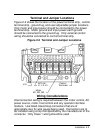
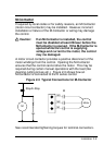
Analog Output
One programmable analog output is available for external
monitoring of the drive condition. This output is available at
terminals CM and MET. The output will be 0-10VDC. The
positive lead of the external meter should be connected to
terminal MET and the negative lead should be connected at
terminal CM. The output condition is programmed in parameter
71-Analog Output Select. The analog output gain (max output
voltage) can be adjusted in parameter 70- Analog Output Scale.
Please refer to the Analog Output Table in Section 3 for the
possible monitoring conditions.
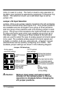
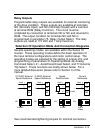
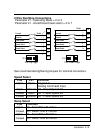
Opto Isolated Inputs
Six digital inputs are available at terminals FWD, REV
, PS3,
PS2, PS1, and MOL to command various output conditions. The
available command condition at the terminal may change
depending on the operating mode selected. These inputs can be
configured for Pull- Up or Pull-Down Logic. The factory setting is
for Pull-Up Logic. The Inputs will be active when connected to
terminal V+ or when utilizing an external 0-24 VDC power supply
with the power supply common connected to terminal CM. The
selection of Pull-UP or Pull-Down Logic is set by jumper J19.
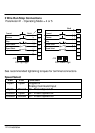
Depending on the function of the command input, a maintained
switch closure or momentary switch closure will be required.
Connection to a PLC, CNC, or host computer are also possible.
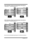
External Trip Connection
Terminal MOL is available for connection to a normally open or
normally closed thermostat in all operating modes. This
connection is available for connection to a motor thermostat or
overload relay. The thermostat or overload relay input can also
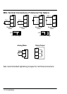
be configured for Pull-Up or Pull-Down Logic. If the state of the
motor thermostat or overload relay should ever change indicating
an over-temperature condition, the inverter will automatically
shut down and give an External Trip fault (F07) or will cause the