


2-10
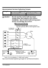
Installation
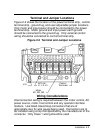
Logic Wiring
All logic and control connections are made at the control terminal
strip located on the motor control board. Screw type terminals
are provided for easy connection to your external control station
and meters. The control terminal strip can be divided into four
major categories as follows:
1) Analog command inputs.
2) Analog outputs.
3) Opto Isolated inputs.
4) Relay outputs.
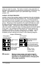
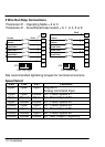
Analog Command Inputs
An external 5kohm potentiometer can be connected at terminals
CM, VIN, and REF. The potentiometer should be connected so
that full resistance is connected from CM and REF. REF is a
5VDC potentiometer reference output. The wiper of the
potentiometer should be connected at terminal VIN. The speed
command input will be recognized at terminals CM and VIN.
When using a potentiometer as the speed command, the Analog
Command Select parameter will need to be programmed to 0 or
1 and jumper J19 will need to be set properly.
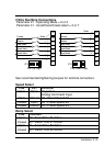
An external speed command of 0-5VDC, 0-10VDC, 0-20 mA, or
4- 20mA can be used instead of a potentiometer at terminals CM
and VIN. The positive lead should be connected at terminal VIN
and the negative lead should be connected at terminal CM. The
Analog Command Select parameter should also be programmed
to 0 or 1 and jumper J19 will need to be set properly.