


2-8
Installation
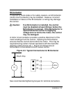
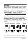
Motor Connections
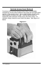
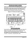
Connect the three phase power leads of the AC motor to
terminals M1, M2, and M3 of the inverter power terminal strip.
The motor ground lead or case ground should be connected to
the inverter chassis ground screw. The motor should be
connected to the inverter at all times during inverter operation.
If additional motor overload protection is required, the use of
suitably sized motor overload relays are recommended. Motor
overload relays should be connected between the motor and
inverter with the relay trip indicator circuit connected into the
external inverter control circuitry to power down or trip the
inverter in the event of motor overloading.
Caution: Overload relays with an automatic reset
feature are not recommended in applications
where an automatic restart of the motor
could cause personal injury or harm. If
manual reset relays are not available, then
the automatic reset feature should be
defeated.
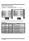
If the motor is equipped with a normally closed thermostat, the
thermostat should be connected at terminals MOL and CM of the
control terminal strip. The inverter will also need to be
programmed to trip if this thermostat circuit opens indicating a
motor overload condition. The inverter will need to be
programmed by adjusting parameter 77-External Trip Select and
placing the proper jumper position on jumper terminals J19.
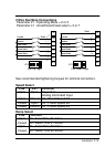
If during initial motor start up the motor rotation is opposite to
that desired, disconnect the input power from the inverter and
wait at least 5 minutes for the bus voltage to bleed off.
Interchange any two of the three motor leads at the inverter
power terminal strip M1, M2, and M3 to change the shaft rotation
of the motor.