


2-12
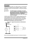
Installation
motor to coast to a stop. The fault or coast to stop operation of
the MOL input terminal is selected by parameter 77-External Trip
Select. The selection of pull- up or pull-down logic is set by
jumper J19.
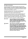
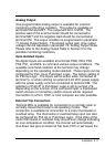
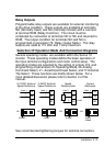
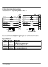
Jumper J19 Input Selection
Jumper J19 is a pin-jumper selector located to the left and below
the control terminal strip (See Figure 2-2). Five jumper positions
are available and are arranged in one group of three positions
and one group of two positions with one shorting jumper in each
group. The group of two located to the right hand side are used
to select the active state of the opto isolated inputs (Pull-Up or
Pull-down Logic). The group of three located to the left hand
side are used to select the type of analog speed command signal
to be used. The available analog speed command signals are
0-5VDC, 0-10VDC, 0-20 mA, and 4-20 mA. A 5kohm 1/2 watt
potentiometer can be used by configuring for 0-5VDC. The
available jumper settings are shown in the following diagram:
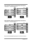
Jumper
J19 Selections
Analog speed
command settings
OPT
O isolated
input settings
0Ć10VDC
Command
Signal
0Ć20mA or 4Ć20mA
Command Signal
0Ć5VDC or Potentiometer
Command Signal
(Factory Setting)
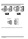
PullĆdown logic inputs are
active when connected to
terminal CM
PullĆup logic inputs are active
when connected to terminal
V+or external 0Ć24VDC supply
with it'
s common connected to
CM.
0Ć3VDC = Inactive
10Ć24VDC = Active
(Factory Setting)
Caution: Remove input power and wait at least 5
minutes for the residual power in the bus
capacitors to dissipate before changing the
J19 jumper positions.