T
ractors,
Lawn
and
Garden
-
110
and
112
SM-2059
(Apr-67)
I
~
.
.
~
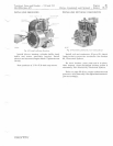
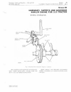
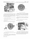
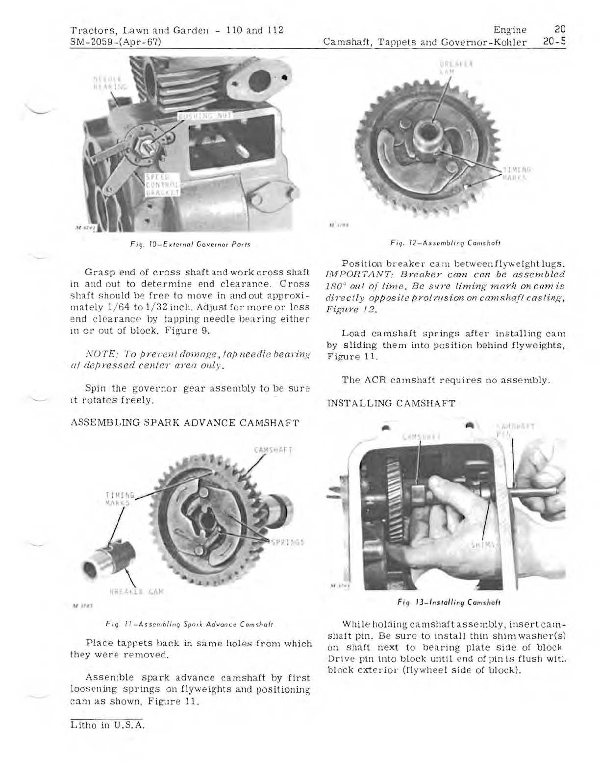
Fig.
IO-Exlcrnal
Governor
Porls
Grasp
end
of
cross
shaft
and
work
crOSS
shaft
in
and
out
to
determine
end
clearance.
Cross
shaft
should
be
free
to
move
in
and
out
approxi-
mately
1/ 64
to
1/ 32
inch.
Adjust
for
more
or
less
end
clearance
by
tapping
neeclle
bearing
eHhel-
in
or
out
of
block.
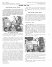
Figure
9.
;VOTE.'
To
pye/
:
cnl
damage,
lap
needle
bearing
(II
depressed
cen/c
'r
aren
oilly.
Spin
the
governor
gear
assembly
to
be
sure
it
rotates
freely.
ASSEMBLING
SPARK
ADVANCE
CAMSHAFT
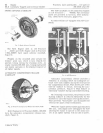
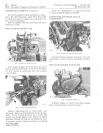
Fig
.
II-Assembling
Spork
Advan~e
Carn,/lOlt
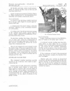
Place
tappets
back
in
same
holes
from
which
they
were
removed.
Assemble
spark
advance
camshaft
by
first
loosening
springs
on
flyweights
and
positioning
cam
as
shown,
Figure
11.
Litho
in
U.S.A.
Engine
20
Camshaft,
Tappets
and
Governor-Kohler
20-5
-.. R
\1
..
t.,
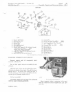
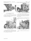
Fig.
12-Asscmbling
Camshaft
Position
breaker
cam
between
flyweight
lugs.
[i'v'JPOR
TJ1
NT:
Breakey
cam
can
be
assembled
180
0
oul
of
lime.
Be
sure
timing
marf~
on
cam
'is
directly
opposite
pyotrusion
on
camshaft
caslin.g,
Figure]
2.
Load
camshaft
springs
after
installing
cam
by
sliding
them
into
position
behind
flyweights.
Figure
11.
The
ACR
camshaft
requires
no
assembly.
INSTALLING
CAMSHAFT
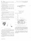
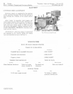
Fi
g
13-/ns/olling
Com
,hofl
While
holding
camshaft
assembly,
insert
cam-
shaft
pin.
Be
sure
to
install
thin
shim
washer(s)
on
shaft
next
to
bearing
plate
side
of
blOCK
Drive
pin
into
block
until
end
of
pin
is
flush
wit:.
block
exterior
(flywheel
side
of
block).


