70
Miscellaneous
Tractors,
Lawn
and
Garden
-
110
and
112
15-4
Lift
Linkage
SM-2059-(Apr-67)
REPAIR-Continued
REMOVING
LIFT
LINKAGE
IN
PEDESTAL
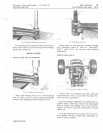
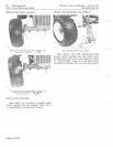
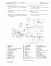
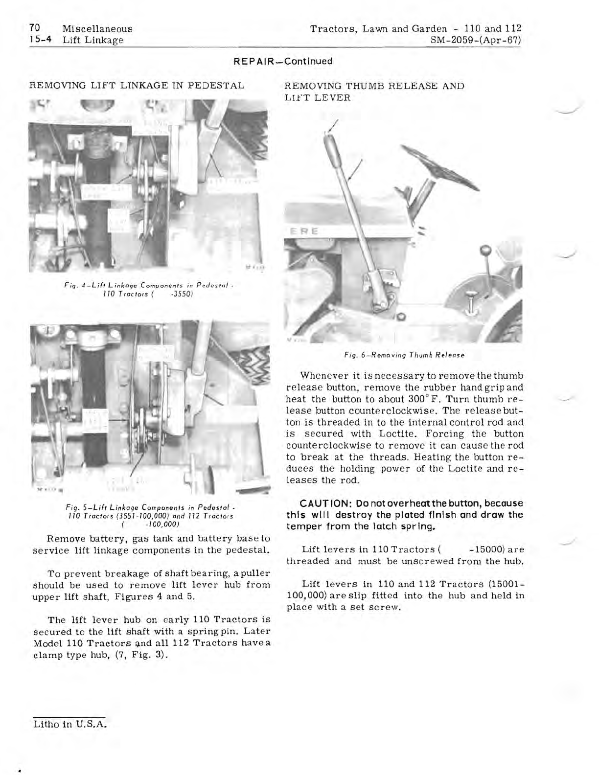
Fig.
4 -
Lift
Linkage
Components
i"
Pedestal·
110
Tractors
(
.3550
)
REMOVING
THUMB
RELEASE
AND
LIFT
LEVER
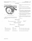
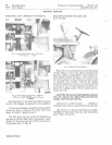
Fig
.
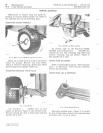
6-Removing
Thumb
Release
Whenever
it
is
necessary
to
remove
the
thumb
release
button,
remove
the
rubber
hand
grip
and
heat
the
button
to
about
300
0
F.
Turn
thumb
re-
lease
button
counterclockwise.
The
release
but-
ton
is
threaded
in
to
the
internal
control
rod
and
is
secured
with
Loctite.
Forcing
the
button
counterclockwise
to
remove
it
can
cause
the
rod
to
break
at
the
threads.
Heating
the
button
re-
duces
the
holding
power
of
the
Loctite
and
re-
leases
the
rod.
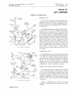
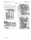
Fig.
5-Lift
Linkage
Components
in
Pedesta/
•
110
Tractors
(3551.100,000)
and
112
Tractors
(
.100,000)
Remove
battery.
gas
tank
and
battery
base
to
service
lift
linkage
components
in
the
pedestal.
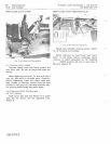
To
prevent
breakage
of
shaft
bearing,
a
puller
should
be
used
to
remove
lift
lever
hub
from
upper
lift
shaft,
Figures
4
and
5.
The
lift
lever
hub
on
early
110
Tractors
is
secured
to
the
lift
shaft
with
a
spring
pin.
Later
Model
110
Tractors
~nd
all
112
Tractors
have
a
clamp
type
hub,
(7,
Fig.
3).
CAUTION:
Do
not
overheat
the button, because
this
will
destroy
the plated
finish
and
draw
the
temper
from
the
latch
spring.
Lift
levers
in
110
Tractors
(
-15000)
are
threaded
and
must
be
unscrewed
from
the
hub.
Lift
levers
in
110
and
112
Tractors
(15001-
100,000)
are
Slip
fitted
into
the
hub
and
held
in
place
with
a
set
Screw.
Litho
in
U.S.A.


